
Editor’s Note: This paper is a response to the June 2024 paper by Mehmet Inan, which can be read here.
The author would like to thank Mehmet Inan for submitting a paper to the International Center for 9/11 Justice’s “Debated Topics Forum.” The author would also like to thank the International Center for 9/11 Justice for developing this “Debated Topics Forum” to facilitate genuine scholarly debate to advance our understanding of the 9/11 crimes. Even though not every detail raised by Inan will be addressed due to space limitations, the damage will be shown to be inconsistent with a Boeing 737-400 and consistent with a Boeing 757-200. Figure numbers that refer to Inan’s paper will be preceded by an “MI” designation.
Inan discusses the importance of a careful review of the evidence when trying to understand what happened at a crime scene. He has surveyed the damage, performed measurements, applied the laws of physics and engineering, and developed a working hypothesis.
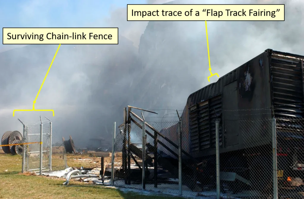
With that said, this paper will underscore the importance of using all available information to validate, or invalidate a hypothesis. Inan’s detailed drawings of the hypothesized Boeing 737-400 recognize the four “Flap Track Fairings” that are located on the underside of the wings and are designed to house the mechanisms controlling the wing flaps (see triangular protrusions from the rear of each wing in Figures MI-9, MI-11 and MI-17). This paper will use the trace of a Flap Track Fairing on the roof of the diesel generator trailer as a key detail to establish the horizontal and vertical location of an identifiable feature of both a Boeing 737-400 and a Boeing 757-200. This trace was not seen in the roof of the generator trailer in any pre-event photographs including a satellite image from September 7th. The appearance of this very noticeable trace in the photographs, during and after the event, indicates that the impacting aircraft was the source of this trace.
Most importantly, the hypothesized approach path established by Inan for a 737-400 has an axial alignment that would impact between columns 12 and 13, which is about 15 feet further north than shown in his other figures. Given the requirement to impact all of the light poles, Inan’s proposed path does not allow the right engine to impact the generator trailer and it does not allow a Boeing 737-400’s outer Flap Track Fairing to create the observed scar. Appendix “A” to this paper provides isometric drawings to illustrate this. The hypothesized path invalidates the 737-400 hypothesis. Other damage that is inconsistent with the impact of a 737-400 into the Pentagon will also be discussed. Significantly, Inan provides no evidence of aircraft parts that would uniquely identify a Boeing 737 and dismisses the significant amount of Boeing 757 specific debris without justification by asserting they were carried abord an impacting Boeing 737.
Dimensions are Important
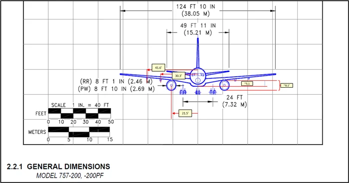
To minimize the potential for measurement errors, where possible the precise path of the aircraft will be determined by the location of the impact trace of the right wing’s Flap Track Fairing. These mechanical fairings, or covers, are a feature of both Boeing 737 and 757 wing designs. Figures 1 and 2 show the location of these fairings in relation to the centerline of a Boeing 757 [1]. They are 4 and 20 feet beyond the outside edge of the engine. These dimensions are estimates based on proportions of the wing-tip to wing-tip distance used as a reference. One dimension of interest, shown in green on Figure 2, is the distance from one Flap Track Fairing to the centerline of the opposite engine. For a Boeing 757-200 this measurement is 63.1 feet.
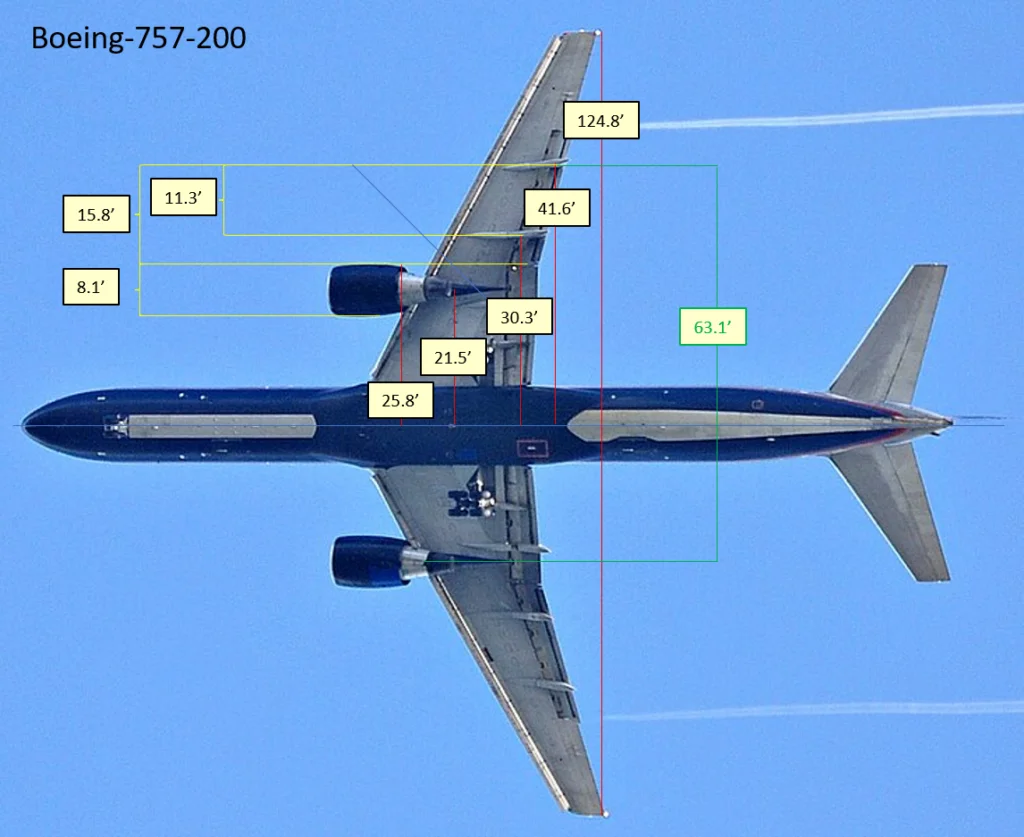
Figures 3 and 4 show the corresponding measurements for a Boeing 737-400 [2]. The Flap Track Fairings are about 1 and 10 feet from the outside edge of the engine. Again, these dimensions are estimates based on proportions of the wing-tip to wing-tip distance used as a reference in Figure 4. The distance from one Flap Track Fairing to the centerline of the opposite engine for a Boeing 737-400 is 46.1 feet.
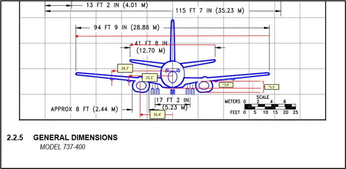
Figure 4 is an underside view of a Boeing 737-400 to show the detail of these fairings and present the dimensions.
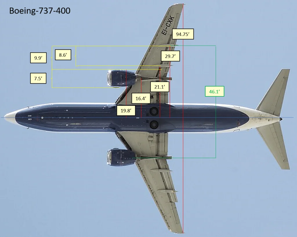
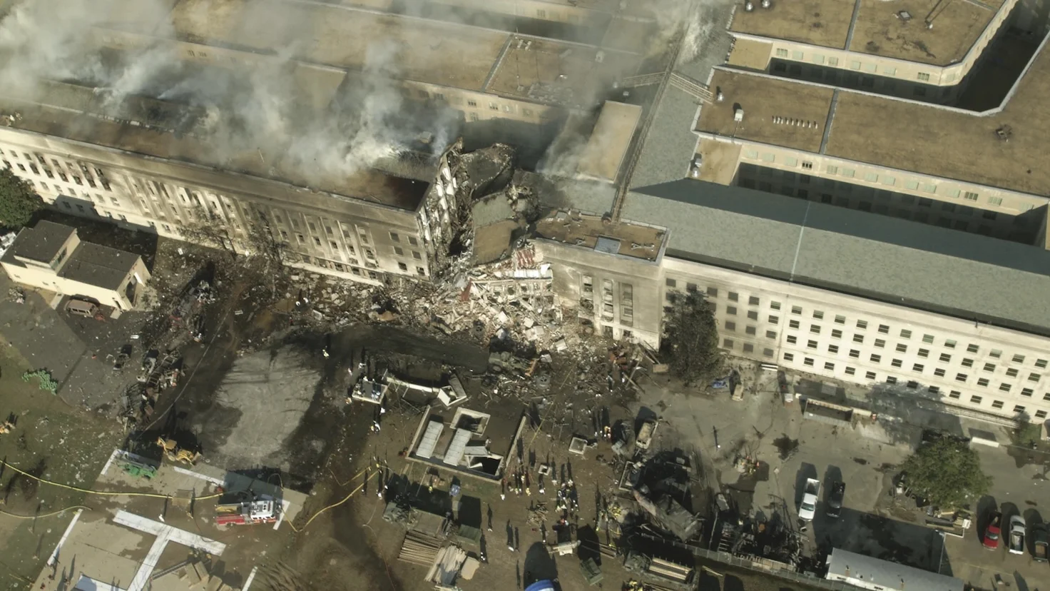
Figure 5 provides an overview of the west side of the Pentagon before 9/11 [3]. This image shows the location of the generator trailer, other adjacent structures, the wire spools, the gouged retaining wall, and the Pentagon facade. While soot can be seen discoloring the center of the trailer roof, there is no hint of the Flap Track Fairing trace in this pre-event image which shows only a smooth rear cabin roof. Additionally, the cabin roof at the front of the trailer has a uniform color that matches the uniform color of the rear. This suggests a satellite image would record the roof as a single color, except for the discolored center.
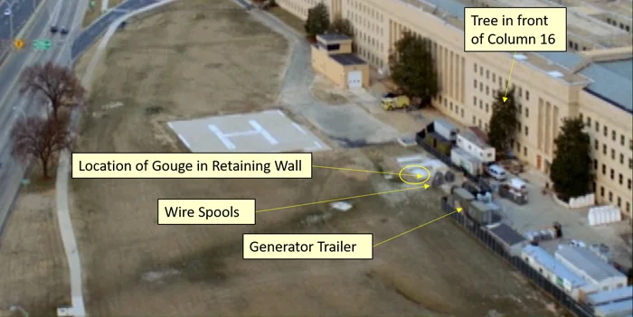
Figure 6 shows the trace of one of these fairing through the top of the generator trailer [4]. The trailer was rotated to the right as the side of the impacting right engine impacted the front-half of the left side of the generator trailer. At the appropriate height, this 52-degree impact would not only rotate the trailer out-of-the-way and toward the right, it would also collapse the front struts of the trailer allowing the trailer to be collapsed downward. This would allow sufficient rotation and descent of the trailer to allow the engine to pass alongside. This impact also created a ‘bullseye’ on the corrugated side of the folded-over forward portion of the trailer’s steel cabin where the corrugated siding was hammered-out smooth. The ‘bullseye’ appears to be approximately 5 ft from the front of the trailer. This marks the exact location where the engine began impacting the trailer. The trace of the Flap Track Fairing on the top of the trailer can be used as an unambiguous data point for the height and position of a specific identifiable aircraft component. Detailed drawings are available in the appendices.
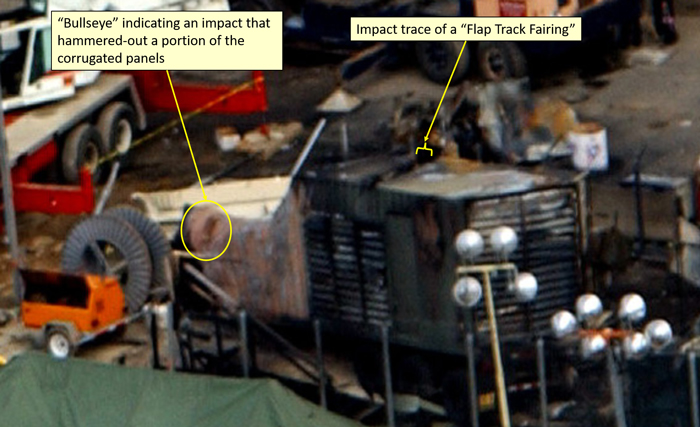
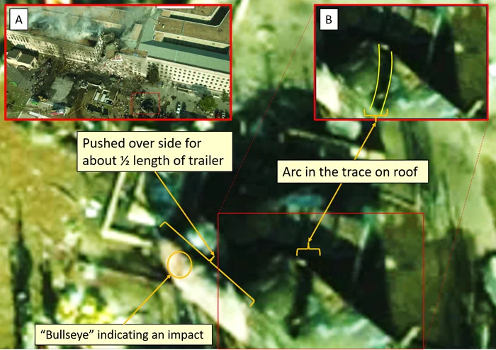
Figure 7 shows an overhead view of the trailer roof in a photo by Scott Boatwright [5]. Compared to the parallel objects on the ground, the final location of the trailer is rotated approximately 30 degrees around the rear wheels. This image shows the trace to be an arc; not a straight line. Such an arc is consistent with the generator trailer being rotated while the Flap-Track Fairing was cutting the trace. At the observed approach speed of 795 feet/sec (542 mph) [6], the contact time of the flap track fairing into the trailers roof would have been less than 2/100th of a second. For this arc to have been captured in the roof, the trailer would have needed a significant rotational velocity. Appendix C provides a series of drawings that illustrate this process.
https://sire-media-ngcdk.fichub.com/generic/photogalleryphoto/1640972.custom.jpg)
Figure 8 shows the total rotation of the trailer around its likely center of mass over the rear wheels. The total rotation is approximately 30 degrees. The imparted rotational inertia from the impact of the engine into the trailer would have caused the trailer to continue rotating after the trace was cut by the Flap Track Fairing. The axial alignment of the approaching 757 would have placed the outer right Flap Track Fairing on a path toward a point on the façade between columns 18 and 19. Once the rotation ceased, the trace is orientated in the direction of column 26 or 27. This suggests a total period of rotation of about 2 seconds before the trailer came to rest at its post impact orientation with its front support struts collapsed.
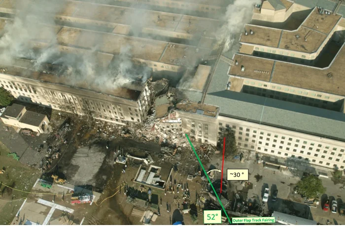
Figure 9 shows the interior of the front portion of the cabin from the front. The interior space shows what appears to be a large rectangular object that appears to have been a control panel, tool lockers or some other wall-mounted unit. The heavy diesel generator equipment would have been mostly over the multi-axle rear wheels giving a center of mass near the rear.
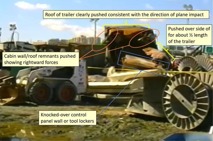
Figure 10 is a satellite image of the Pentagon from September 7, 2001 and will be used to establish all relevant dimensions. Using this single image eliminates problems with parallax and other distortions affecting measurements. It is believed that a resolution of about one foot (±1 foot) is reasonable when working with this image. This resolution is more than adequate for the analysis presented in this paper. Because of the very slight position of the satellite to the east, the edge of the visible roofline on the west represents a nearly perfect location of the column rows. The satellite’s eastern location can be verified by the visibility of the “whiteish” wall on the west side of the interior courtyard and shadows cast around the heliport firehouse.
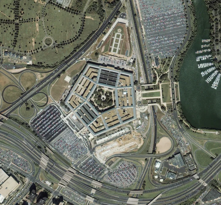
Figure 11 shows the relevant section of the satellite image along with dimensions and other information. The first inset, “A,” shows a rotated version of Figure 5 which identifies the generator trailer and two other adjacent buildings. The second inset, “B,” shows a detail of the generator trailer with dimensions that can be estimated once its length has been determined from the satellite image. The area between the white lines topped with red dots locate the side air intake vents. The third inset, “C”, shows the trailer with and without outlines. The outline of the trailer is bounded by the consistent light color of the roof with the only deviation being the area in the center that was discolored by diesel soot. While the soot can be seen discoloring the center of the trailer roof, there is no hint of the trace in this image. The fourth inset, “D,” provides a larger view of the trailer in the satellite image.
Because photographs showing the front of the trailer before the event do not have sufficient granularity to gauge the size of the gap between the front of the trailer and fence along the front accurately, a five-foot extension of the trailer will be presented as a sensitivity in Appendix “A” for completeness. This extension is shown as a red outline in inset “C.”
The basis of all measurements is the length of the bay of the facade which is labeled as 450 feet.
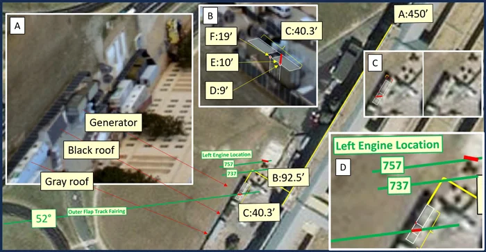
The image shows six key dimensions plus some additional annotations using green lines and green text.
A. Length of window bay. This is 450 feet long and provides the primary basis for all dimensions
B. Distance from facade to the far side of generator trailer is about 92.5 feet
C. Length of generator trailer is about 40.3 feet
D. Distance from back of the generator trailer to the beginning of the first vent is about 9 feet
E. Distance from back of the generator trailer to the Flap Track Fairing scar is about 10 feet
F. Distance from back of the generator trailer to the end of the third vent is about 19 feet
The green lines are important because they establish the location of the outer Flap Track Fairing that impacted at 52 degrees as well as the location of the opposite engine in relation to it. The location of the opposite engine is shown by two short parallel green lines. These two additional green lines are associated with either a 757-200 or a 737-400. The green line identified as the “737” is separated from the fairing trace by 46.1 feet while the green line identified by the “757” is separated by 63.1 feet. The “757” line intersects with a red line segment that locates a gouge in the retaining wall that has been associated with the impact of an aircraft’s left engine.
Figure 12 shows before and after images near the gouged retaining wall where the red line segment was drawn. Figure 12A shows seven wire spools from a photo taken prior to September 11. These spools are in locations consistent with the satellite images in Figures 10 and 11. The shadows do not have sufficient resolution to discern the location and size of each spool. Figure 12B provides an identification using colors and numbers. Spools 1, 2 and 3 are near the generator trailer, while spools 6, 5, 4 and 7 are seen close to the retaining wall. The spool labeled 4 is near the retaining wall and closest to the Pentagon facade.
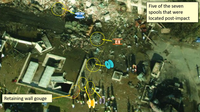
Figures 12C and 12D show the location of the remaining spools after impact. Spools 5 and 6 are in the same location as shown in Figure 12B while spools 7 and 4 are knocked toward the facade. Figure 13 shows Scott Boatright’s overhead photo, cropped to show the post impact location of the spools more clearly.
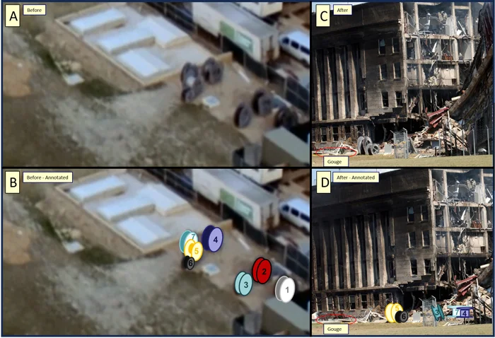
These resulting spool locations are consistent with the bottom of the left engine of a 757 impacting the retaining wall while the front/right side of the engine impacted spool 7 which knocked it into spool 4 sending both traveling rightward toward the facade. Meanwhile, spools 5 and 6 remained unaffected because the engine passed to their left without striking them as the wing went above them due to the clearance between the engine and fuselage shown in Figure 1.
According to Figure 11 if the outer Flap Track Fairing of a 737 created the trace, the path of the 737-400’s left engine would have impacted spools 4, 5 and 6 but not 7. There is no possibility of any spool traveling in the reverse direction of the engine impact that could create the damage to the retaining wall as asserted by Inan, “This notch in the ventilation wall was most probably made by the cable spool indicated in Figure MI-10.” This analysis of the spools, by itself, invalidates the 737-400 hypothesis and bolsters the 757-200 hypothesis. The appendices to this paper provide graphical representations of these spool impacts and an estimate of their movements.
Location of the Right Wing-Tip
One of the key parameters for understanding the size of the impacting aircraft is the location of the right wingtip. This is a critical dimension because on a Boeing 737-400 there is about 47 feet from the centerline of the fuselage to the wingtip. This dimension for a Boeing 757-200 is about 62 feet. While there are no definitive marks that explicitly answer this positional question on the façade, there is evidence that the right wingtip very nearly reached column 21 and solidly impacted column 20. Figure 14 shows significant debris on the window sill between columns 20 and 21. This would not have been expected if the right wingtip only grazed the edge of column 20 as Inan’s detailed drawings in Figures MI-11 and MI-17 show. However, careful examination of Inan’s Figure MI-9 shows that the tight path through the severed light poles requires Column 20 to be missed by a more than 10 feet.
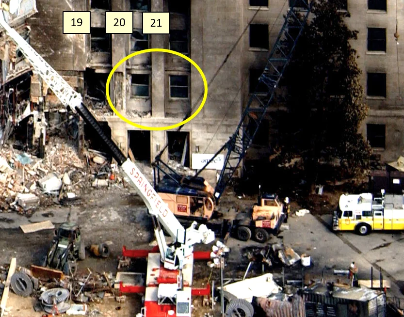
Figure 15 shows that the frame of the window between columns 20 and 21 has its left side bent. Because this window frame is constructed with 8” square steel tubing, a significant impact would have been needed to create this observed deformation. Consequently, Inan’s detailed drawing (Figures MI-11 and MI-17) should have the impacting aircraft shifted at least 10 feet to the right and probably more because the right-wing tip barely touches column 20 in his analysis and cannot account for the observed damage. Detailed graphical analysis of these distances is presented in the isometric drawings in Appendix A.
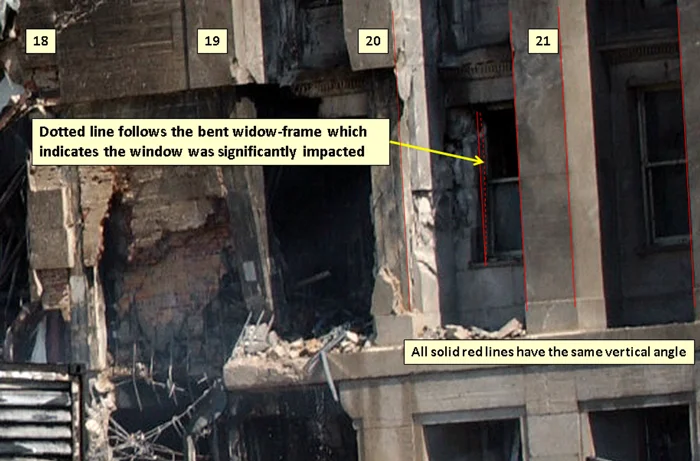
Figure 16 is an annotated version of Inan’s Figure MI-9. The column locations that are added are based on actual scale drawing of the wall extracted from the Arlington Fire Department’s After-Action Report [7]. Five columns of interest are marked (columns 9, 13, 14, 20 and 21) and their size is approximately shown to scale. Inan’s Figures MI-16 and MI-17 rely on the sizes of the column shown in the ASCE Pentagon Performance report that are shown 3½ times larger than actual size for the purpose of color-coding amounts of damage sustained by the columns. The uncolored columns in Figure MI-11 shows the actual column sizes (e.g., see the little squares in column row 5).
Inan shows the 737-400 approaching along a straight path constrained by the need to impact all five light poles. With this axial alignment, the nose impacts the Pentagon façade to the left of columns 13 (e.g., between columns 12 and 13). The plane’s dimensions are verified to be consistent with a Boeing 737-400 having a wingspan of about 94 feet. However, the right-wing tip cannot reach column 20 and the right engine does not clip the corner of the diesel generator trailer. Given the approaching aircraft is at an altitude allowing the Flap Track Fairing to create the trace through the roof of the trailer, the engine, which hangs about 6 feet below the wing, could not impact the generator trailer unless it were shifted 10 or more feet to the right. However, if the 737 is shifted to the right, then the light poles #2, #4 and #5 could not all be hit solidly enough to sever the light poles, as was observed.
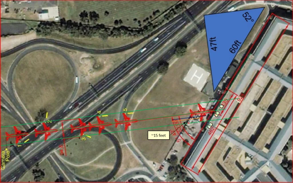
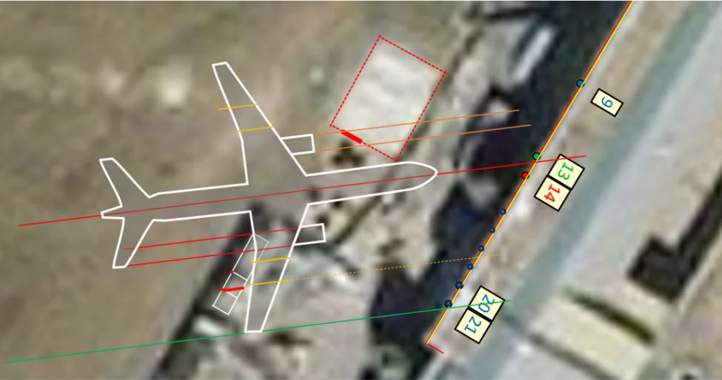
Figure 17 zooms into this image to focus on establishing the location of the Flap Track Fairing trace on the trailer in the satellite image. The green lines provide a wingtip-to-wingtip envelope of the hypothesized 737-400. The orange line shows the location of the outer Flap Track Fairing and the short blue line provides the outside limit of the right engine. The thick red line on the roofline of the generator trailer above the rear air intake vent panel shows the location of the observed trace.
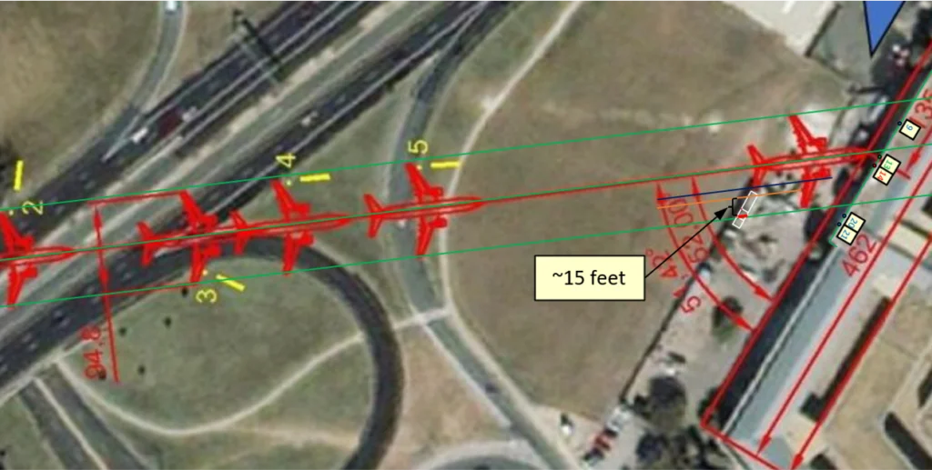
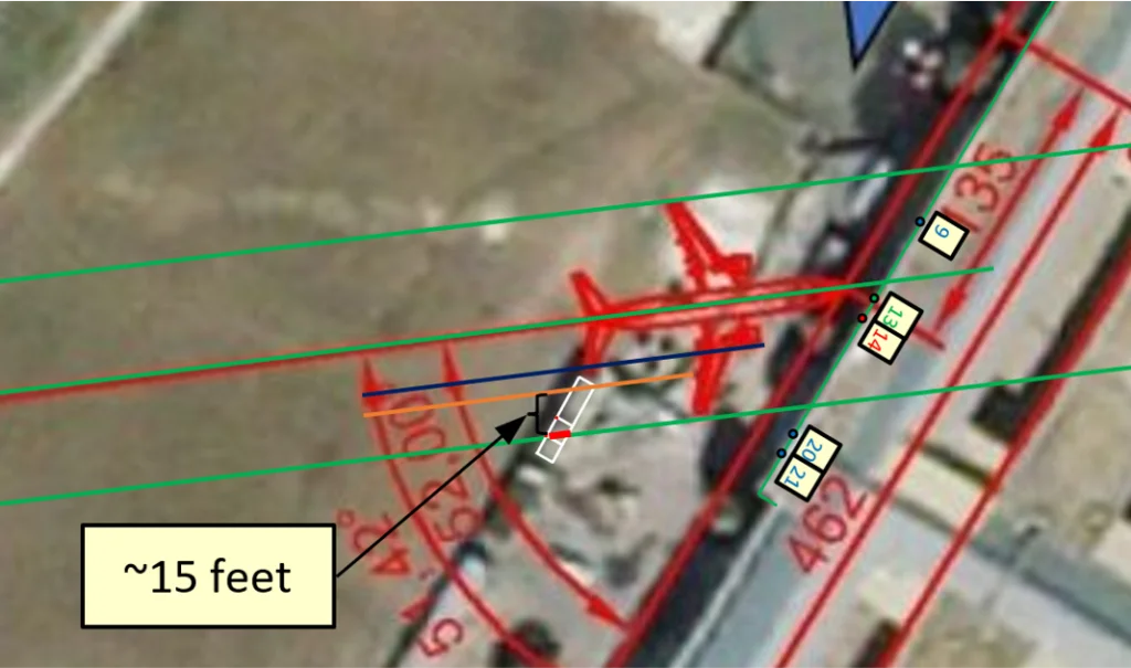
Figure 18 expands the detail of the hypothesized 737-400 approach. As shown, the nose will impact to the left of column 13. The blue line shows the position of the right engine which indicates no possibility of an impact with the generator trailer, even though this blue line is placed on the farthest outside edge of a wide, blurry red outline of the 737. The orange lines show the path of the outer Flap Track Fairing. The outer fairing is about 15 feet from the thick red line that indicates the trace on the roof of the generator trailer.
If the plane was shifted 15 feet to the south to align the Flap Track Fairing and the trace, the approach path through the light poles would likely miss both light poles #2 and #4 and the nose of the plane would impact to the right of column 14 (e.g., between columns 14 and 15).
Finally, the lower green line shows the right-wing tip does not impact column 20. The column locations along the façade are from an actual scale drawing of the wall extracted from the Arlington Fire Department’s After-Action Report [7].
As shown in Figure 19, a Boeing 757-200 traveling along approximately the same axial path as hypothesized in Figure MI-9 almost fits the observations perfectly. With an axial alignment toward the right of column 13, the outer Flap Track Fairing aligns with the trace in the generator trailer roof. The right engine impacts the trailer at approximately the middle of the front half of the trailer where the ‘bullseye’ records an impact. Additionally, without considering any yaw rotation, the outer right wingtip would impact column 21. Wire spool 7 would be impacted while wire spools 6 and 5 would be underneath the left wing between the fuselage and engine. The left engine is perfectly aligned to impact, and gouge, the retaining wall section which is shown in red. While more detailed explanations about the 757 Impact can be seen at 911Speakout.org [8], the measurements in this analysis are more precise.
Surviving Corner Segment of a Chain Link Fence
One of the minor structures that can provide insights into the dimensions of the impacting aircraft is a surviving corner segment of the chain-link fence that had surrounded the generator trailer. Figure 20 shows this surviving corner section is largely undamaged and, including the barbed-wire, it is approximately half the height of the trailer. Two sections of the fence have been knocked-down between the surviving corner segment and the continuation of the fence along the side of the trailer. As shown in Figure 18, the path of the right engine of a Boeing 737-400 would have impacted this corner fence segment. However, as shown in Figure 19, the right engine of a Boeing 757-200 would have impacted the fence at the location of the knocked-down sections while leaving the corner segment unaffected. The alignment of this fence segment can be seen in the isometric drawings in Appendix “A.”
Aircraft Debris
It seems reasonable to expect that a claim stating the impacting aircraft was a Boeing 737-400 would be accompanied by a discussion of debris associated with the hypothesized model of aircraft. Inan explains the presence of Boeing 757 debris as having been carried inside the 737 and then disgorged as the plane was destroyed without leaving any debris of its own. “… these parts must be planted inside the aircraft with weak connections, such as used for transportation [and] … they were detached from the aircraft immediately at impact time and continued their way straight toward the exit hole. These parts are not parts of the aircraft that impacted the Pentagon.” In this, Inan acknowledges that the available debris is consistent with components of a Boeing 757. While he only specifically mentions two pieces when he says, “The plane was empty of its seats and passengers. It was rigged with a 757-200 landing arm, a prerecorded Flight Data Recorder and a bomb.”
However, in his short list of explicit aircraft parts, he excludes a plethora of other parts that were photographed in and around the Pentagon. For example, many discussions about the aircraft debris show parts of a Rolls Royce RB-211-535 engine which is the type that powered American Airlines flight 77. The Boeing 737-400 uses the CFM International CFM56 engine for which no discussion of debris from this class of engine can be found in the literature about the Pentagon. Figure 21 shows some of the parts of the RB-211-535 engine.
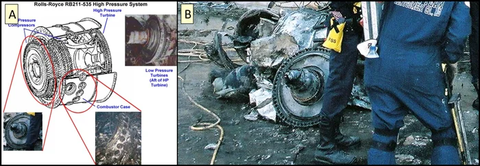
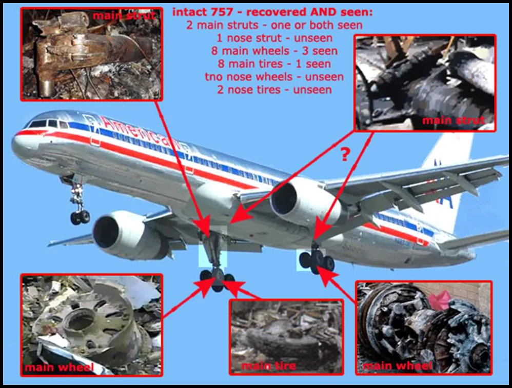
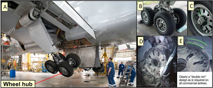
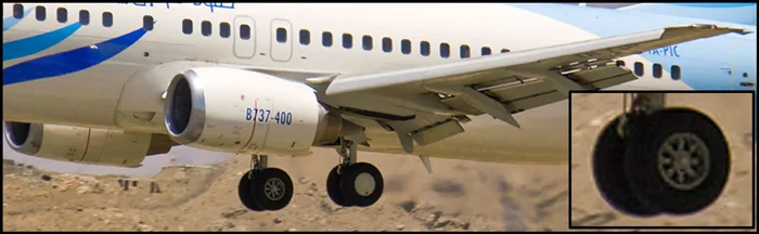
Figure 22 is an infographic showing some Boeing 757 parts that were observed in the debris. Figure 23 shows the unique rims that were used by the Boeing 757 and photographed outside the C-Ring exit hole immediately afterwards. Figure 24 shows the wheelsets of a Boeing 737-400. Boeing 737s do not have doors covering the main landing gear doors during flight. The wheels become flush with the fuselage when retracted and, consequently, they have streamlined covers on one side of the wheelset. To lighten the wheels of aircraft, the interiors are not solid but have cut-outs of various sizes to create “spokes.” The inner wheel rims of the 737 have cut-aways that are more wedge-shaped than the 757 which are smaller and more tear-shaped.
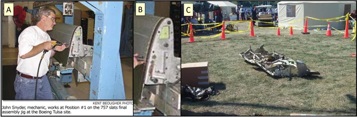
Finally, Figure 25 shows a leading wing slat for a Boeing 757 that was recovered and is compared to a similar slat in a machine shop. More documentation about 757 debris can be seen at 911Speakout.org [9].
An Asserted Case for Internal Explosive Detonations?
Inan asserts that there were explosive detonations that damaged a second-floor slab and created over-pressure waves that blew a large “garage door” open. This garage door opened into AE Drive through the C-Ring wall.
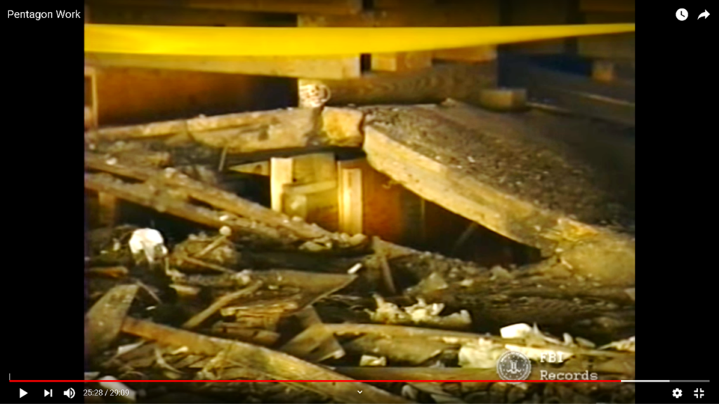
He says, “In ‘[the ASCE’s] Figure 5.27 Breached second-floor slab,’ see Figure MI-18, this slab is shown from the second floor. This upward deflection is the consequence of an overpressure under this area. Such an overpressure can only happen in case of explosion under this area.” Then he says, “That means there was also a bomb inside the aircraft. This bomb also continued its way straight forward and exploded when it reached this orange area where the slab deflected upward. The overpressure of this explosion spread in all direction in the first floor destroying the roll-up door in ring C and windows between columns 4 and 8 in ring E.”
This damage to the second-floor slab was the topic of a recent Debated Topics Forum paper that identifies the source of the damage as the kinetic energy of the rapidly rotating jet engines [10] which were forced to redirect their motion chaotically due to torques from multiple impacts with columns and the dynamic effects of gyroscopic precession. Analysis of the aircraft approach and impact provides an explanation of how the left engine of the 757 entered the Pentagon, with a documented trajectory through the columns. Impacts with columns along this path would create a tumbling and bouncing 5-ton gyroscope whose trajectory would take it directly under the uplifted slab. The tenting of the slab, shown in Figure 26, reflects a mechanical snapping that would be characteristic of mechanical impact damage, not a detonation from below. Explosives of a significant scale would be very unlikely because Major David King was near the location of this alleged explosion and yet was not injured by what would have been a massive explosion.
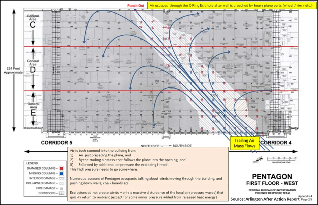
Regarding Inan’s comment about the devastation of over-pressurization “destroying the roll-up door in ring C and windows between columns 4 and 8 in ring E,” it is clear in this comment Inan neglects the phenomena of a trailing air mass behind an aircraft. The reality of a trailing air mass is observed in Figure 27. This image is from a video of a C-130 which shows crew members sitting in an area where the winds from the trailing air mass are approximately equal to the forward speed of the aircraft.
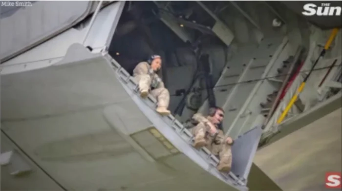
A trailing air mass would have attempted to follow the aircraft into the Pentagon. However, the trailing air mass would “pile-up” and create an over pressurization inside the Pentagon as well as near the façade that would deflect the trailing air mass to the north-west while simultaneously creating a very high pressure inside the Pentagon. The sudden insertion of an air volume equal to the volume of a 757-200 would, by itself, create a significant increase in air pressure that would be observable as winds inside the Pentagon capable of slamming doors and even puffing out a large surface-area garage door. The trailing air mass would amplify and sustain this effect for a short transitory period. Figure 28 shows how this would look from an air pressure perspective. This was explained in the video, “Peer Review of Barbara Honegger’s Parallels Between the WTC and Pentagon Evidence and Why It Matters [11].”
Conclusion
This paper refutes the multiple hypotheses that were proposed by Inan that a Boeing 737-400, not a Boeing 757-200, impacted the Pentagon and that it carried a bomb that did internal damage when it exploded. The trace created by the outer Flap Track Fairing on the roof of the generator trailer was used to locate the approaching aircraft with high precision. From this and the required path through the five light poles, the 737 hypothesis was rejected because the damage to the generator trailer, selective displacement of the wire spools, survival of the corner fence segment, and the damage to the window between columns 20 and 21 are inconsistent with the geometry of the hypothesized 737-400. Shifting a 737 by approximately 15 feet to the south would align the Flap Track Fairing with the observed trace, but this would create other inconsistencies with the observations. The two aspects of damage attributed to a bomb carried into the Pentagon on a 737-400 can be explained by gyroscopic precession of the high-speed rotating engines and over-pressurization caused by the sudden insertion of an object with the volume of a large aircraft and the physics of a trailing air mass.
Appendices
There are three appendices that provide graphical information about the impacts.
- Appendix-A_Rebuttal_to_737-Isometric_Comparison_737_vs_757.pdf: This compares the impact of a Boeing 737 and a Boeing 757 from two interrelated isometric perspectives (overhead view and a view from the rear before impacting the generator trailer). Dotted lines connect many of the objects in each perspective. Due to the lack of granularity in pre-event photographs, a second page illustrates a sensitivity analysis with the generator trailer assumed to extend another 5 feet toward the front. A third page has two diagrams showing the 757 from the rear with the generator trailer front struts collapsed to show the clearance between the trailer and the right engine as the trailer is reoriented and collapsed. The right-most image shows the 757 in a post-generator trailer impact orientation that has the left wing angled down so the left engine impacts the retaining wall. Because the 737-400 does not impact the generator trailer, there is no need for similar diagrams for a 737 scenario.
- Appendix-B_Rebuttal_to_737-the_757_Impact_Sequence.pdf: This series illustrates the approach and impact of a Boeing 757 into the Pentagon. Because the generator trailer is not impacted and there is no yaw rotation before the impact into the façade to account for, similar drawings for a Boeing 737 approach sequence are not necessary because Figure 16 to 18 adequately describe the approach and impact.
- Appendix-C_Rebuttal_to_737-the_757_Generator_Sequence.pdf: This series illustrates the approach and impact of a Boeing 757 into the generator trailer. The emphasis in these drawings is an explanation of the creation of the arc in the Flap Track Fairing trace on the roof of the trailer. Similar drawings for a Boeing 737 approach sequence are not necessary because the outer Flap Track Fairing is about 15 feet short of the trace.
End Notes
- Boeing Corporation, 757-200/300 Airplane Characteristics for Airport Planning, p.13, August 2002, https://www.boeing.com/content/dam/boeing/boeingdotcom/commercial/airports/acaps/757.pdf
- Boeing Corporation, 737 Airplane Characteristics for Airport Planning, p.32, September 2013, https://www.boeing.com/content/dam/boeing/boeingdotcom/commercial/airports/acaps/737.pdf
- 9/11 Documentary | What Happened at the Pentagon (Figure 5 at time 8:26 in YouTube; 8:54 in HD DVD), https://youtu.be/aa03qaBP7Ws?si=EcD6U8Px-ubjI7Jy&t=506
- TSGT Cedric H. Rudisill, USAF, https://commons.wikimedia.org/wiki/Category:Aerial_photographs_of_the_Pentagon_on_14_September,_2001#/media/File:Defense.gov_News_Photo_010914-F-8006R-003.jpg
- Scott Boatwright, https://www.wkar.org/wkar-staytuned-update/2016-09-02/9-11-inside-the-pentagon-post-attack
- Chandler and Coste, Chapter 11: Pentagon Security Camera Analysis [subchapter Plane Image Analysis], https://youtu.be/SunhDlCMJJc?si=RUF3WyQwY7cwYGZ1&t=460
- Arlington County After-Action Report on The Response to The September 11 Terrorist Attack On The Pentagon, https://911digitalarchive.org/files/original/539af7c122c3161721cc688e91b0ab53.pdf
- Chandler and Coste, Chapter 8: Plane Impact Analysis, https://www.youtube.com/watch?v=fzF5smjFVxc
- Chandler and Coste, Chapter 12: Aircraft Debris, https://www.youtube.com/watch?v=amvxGqCmYkc
- Coste, 2024, “Controversy About the Uplifted Second-Floor Slab at the Pentagon: Identifying a Likely Source of Upward Mechanical Impact”, https://ic911.org/debated-topics-forum/forum/controversy-about-the-uplifted-second-floor-slab-at-the-pentagon-identifying-a-likely-source-of-upward-mechanical-impact/
- Coste, Peer Review of Barbara Honegger’s Parallels Between the WTC and Pentagon Evidence and Why It Matters, https://youtu.be/7nxdThV4egA?si=4emeRbpGjqQfuNJF&t=2569
