Editor’s Note: This paper is a reply to the January 2025 paper by Wayne Coste, which was a response to the June 2024 paper by Mehmet Inan. For a concurrent thread stemming from the same original paper, see Inan’s June 2025 reply to David Chandler’s January 2025 response to Inan’s June 2024 paper.
I thank Wayne Coste for his comments about my paper. I also thank IC911 for permitting scholarly discussion about 9/11 issues for the purpose of understanding what really happened in that day. I hope we will be able to get a real discussion and discover the truth of 9/11.
First of all, Wayne Coste is not using a CAD system which permits to get precise dimensions. Without such system, the precision of his claims remains poor. All calculations are meaningless. It is better to download dimensional 2D or 3D drawings from Boeing’s web site. Then using them in a CAD file becomes easy and very precise.
Before deeper considerations, here are some minor aspects:
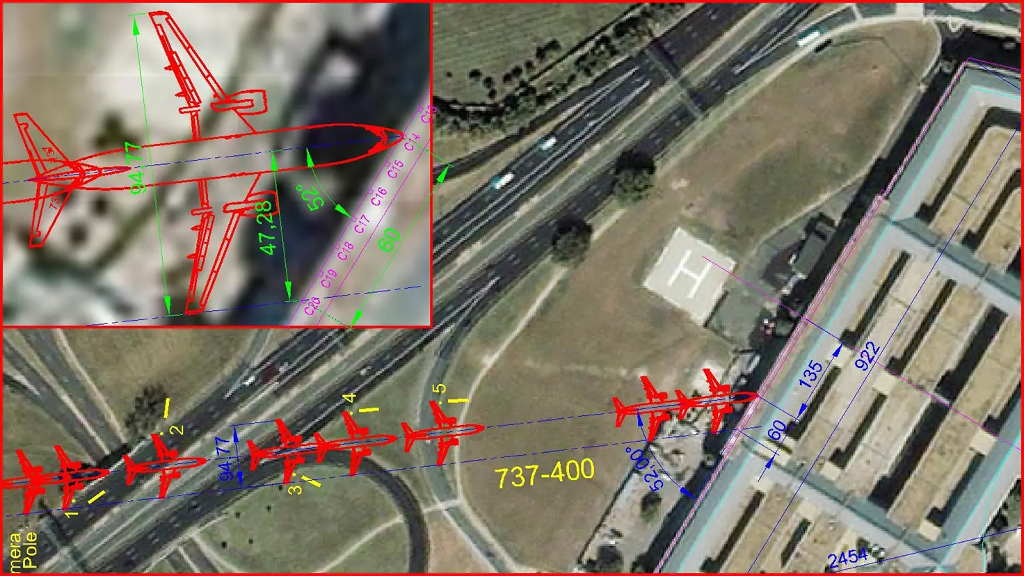
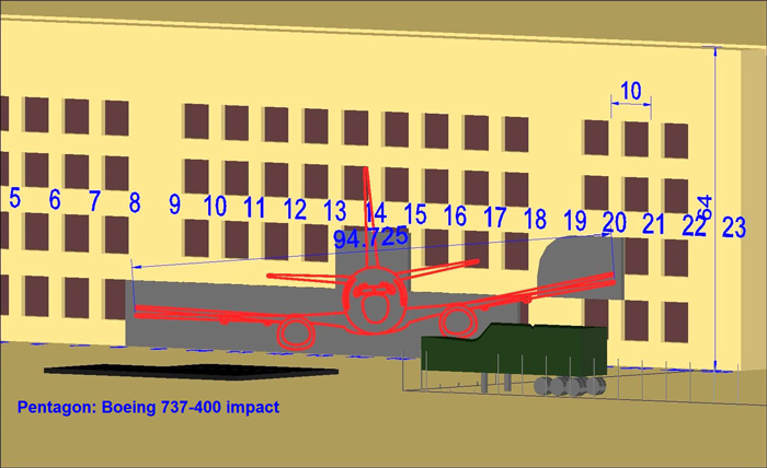
- Wayne Coste dares to simulate the rotation of the plane when it impacts the generator trailer. But it is impossible to measure or calculate any rotation angle. We only know the speed of the plane is very high, and the trailer was impacted at its light section. So, the rotation is very small. It only injects some imprecision in the position of the plane far from the façade reducing the value of any evidence in this area, including the light poles. The best precision for the measurement of the wingspan of the plane can be attained by calculating the wingspan from the damage span made by the right wing on the façade of the Pentagon. This damage span is 60ft, the approach angle is 52°, and the aircraft wingspan is 94ft.
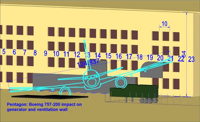
- The approach of the plane in my initial figure 9 was made on basis of original dimensional CAD drawings of the 737-400. Using Google earth dimensional measurement, I updated my initial figure 9 for better precision, see figures 1 and 2 below. The approach of the 737-400 remains consistent with the impact to the 5 light poles while the fuselage enters at column 14.
- Wayne Coste uses many perspective pictures for locating objects. Such images are not dimensional. We cannot measure anything from them. Some of them are undated, such as in figure WC5 (Wayne Coste figure 5). As it is undated, it cannot be used as reference for 9/11. It is wrongly used as reference for the positions of the cable spools before the impact.
- The description of the flap track fairing is not consistent with a 757-200 impacting the generator trailer and the ventilation wall. In such impact, the plane is too oblique and the flap track fairing is too high above the generator trailer.
- The right wing tip of the plane is extended to be nearly on column 21 while there is no evidence anything impacted between C20 and C21.
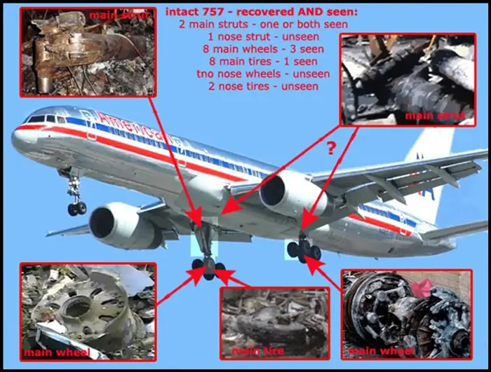
- Wayne Coste shows many 757 landing gear debris inside the Pentagon. All are near the exit hole in ring C where such plane parts could not reach; only planted plane parts can reach this area.
- Wayne Coste also shows two 757 engine parts. But both are individual parts dismounted before the impact. And their location after the impact is unknown. These cannot be used as evidence.
- Wayne Coste dares to show a leading wing slat of 757 in the middle of the lawn days after the impact. But on the day of the impact, the lawn was carefully cleaned up for gathering all debris of the plane. Using this slat as evidence is not valid.
- Wayne Coste claims the uplifted second floor slab is made by the plane engine gyroscopic effect due to the rotation of the engine. This area is far inside the building. At the impact, the engine is damaged and its rotation stops very quickly. There is no more gyroscopic effect so far inside the building.
One positive point from this rebuttal is that it forced me to redraw the approach of the plane with better precision. But let’s analyze the rebuttals more precisely.
The approach path and damaged light poles
The image I used in initial figure 9 was drawn first in 2006. At that time, I did not have enough information and did not look for more precision. For example, I did not consider the AA columns’ positions. Also, the satellite making the picture is not perpendicular. On basis of the south-west corner shadow, I considered moving the roof to get the ground floor. I also took the façade of the Pentagon as reference dimension of 924 ft; it is actually 922 ft.
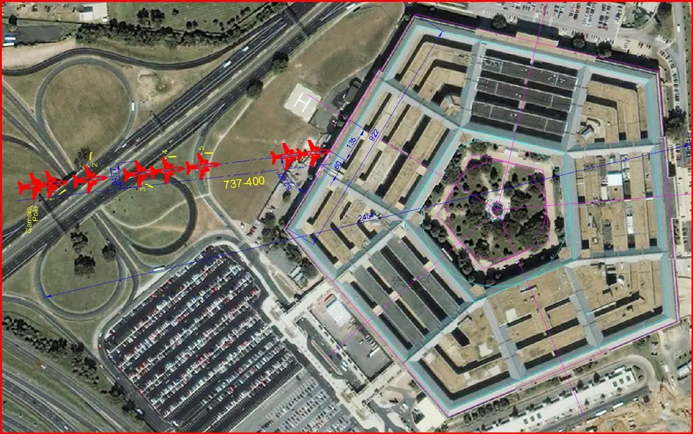
The length reference must be considered from Google earth image with the biggest visible distance. The plane impacted the ground floor; the roof could not be considered. For finding the ground floor the best reference is the inner Pentagon garden in the middle. The five roads are at ground level and are visible in the five sides. Considering these two references, the new dimensional construction is in figure 1. Figure 2 shows the same drawing with better precision.
The 737-400 plane actually impacts all 5 light poles before impacting the Pentagon at column 14, 135 ft from the middle of the facade.
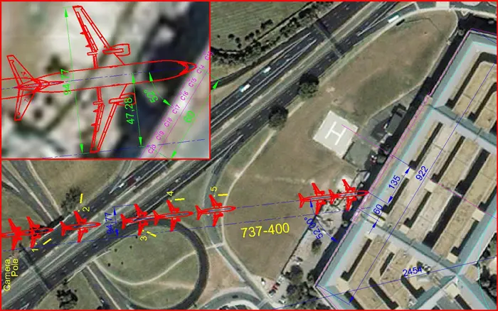
’Flap Track Fairings’ trace on top of the generator trailer
Although it is meaningless, the trace on top of the generator trailer is probably made by some part from the plane, because it is parallel to the damage made by the engine. The flap actuator is one of the possible parts that made this trace, but it is much higher. During the approach path of the plane, the right wing of 737-400 impacted light poles 1 and 3 near the flap actuator. These impacts may have damaged the flap actuator, making it hang down. When the plane impacted the generator trailer, the hanging flap actuator probably did the trace on top of the trailer. Figure 3 shows the 3D construction of 737-400 showing the flap actuator aligned with this trace.
Cable spools and broken ventilation wall
Figure WC5 is an extract from a Youtube video. But it does not fit to the satellite image from 9/7/2001. The cable spools are shown in rolling position. But the spools positions must be referred to figure WC11C-D. In this image, there are only 3 spools near the ventilation wall. The spool number 6 does not exist. Also, the numbering of spools in figure WC-12 is not consistent with satellite image from 9/7/2001.
The only fact we can say is that spool 7 crossed the ventilation wall during the impact. Its actual precise movement cannot be drawn, except that it was laying on the ground. The movement of such spool starting from ground and crossing the ventilation wall would break this ventilation wall at the ground level as it happened.
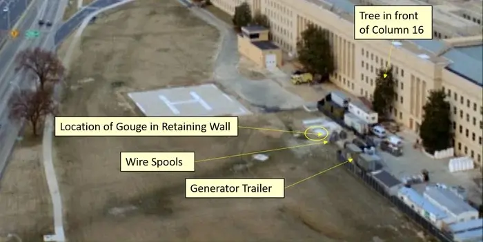
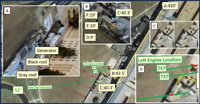
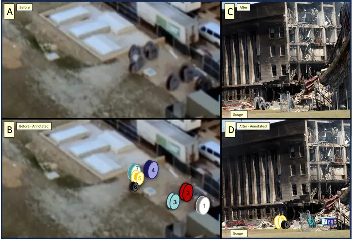
Figure 4 shows the 3D drawing of the approach of a 757-200 impacting the ventilation wall and the generator trailer. It is clearly visible that the plane is too much oblique. The damage on the façade of the Pentagon is not consistent with such impact.
About the left engine impact to the ventilation wall (argument made by Wayne Coste), as the plane was descending, there should be traces of the impact of the left engine to the ground from the ventilation wall to the façade. There is no such trace in the ground. We can definitely say the ventilation wall was not impacted by the left engine of the plane. It was broken probably by the spool 7.
Location of the Right Wing-Tip
The simulation made by Wayne Coste in his appendix b is wrong for several aspects:
- The precision of the simulation is bad. It is not made on a CAD system.
- The center of rotation should be the right engine impact area; not the red circle in the middle of the fuselage.
- At any time, the tail rotates the aircraft in order to get the movement of the plane aligned with the tail. In this simulation the plane moves laterally.
- The impact of the plane was straight aligned with the fuselage. That made the whole fuselage enter the building between columns 13 and 15. The back side of the fuselage did not impact the windows between C13 and C12, as claimed in this simulation. The window’s glass is not broken and there is no impact trace on the frame of the window.
- As the entry of the plane is aligned with the fuselage, if any rotation happened at engine impact with the generator trailer, the path of the plane also changed in order to be aligned with the fuselage. In that situation, the rotation of the plane should make the right wingtip impacting more rightward and damaging even C22. But I do not speculate for calculating any rotation. The plane’s entry direction is about 52° from the façade. This is consistent with the exterior light poles and interior damage. That proves the alleged rotation could be considered as null, because exterior and interior damages are aligned with this approach direction of about 52°.
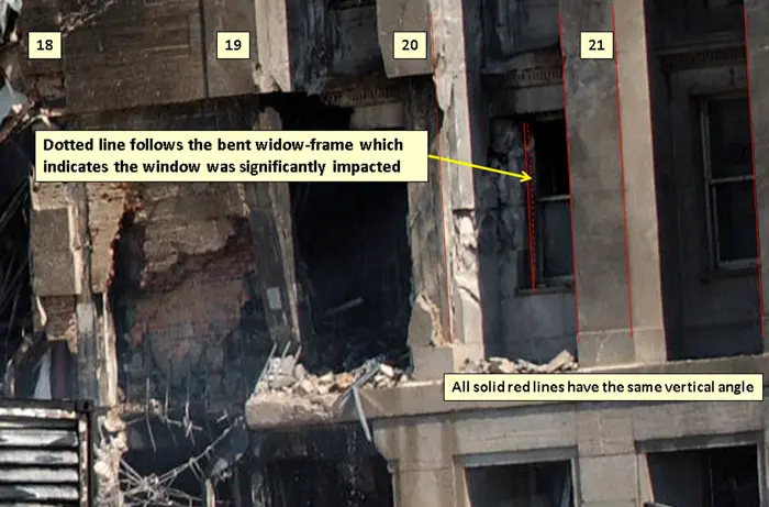
The right wingtip missing column 21 is not important. The important information is the precise location of the right wingtip. Wayne Coste claims “While there are no definitive marks that explicitly answer this positional question on the façade, there is evidence that the right wingtip very nearly reached column 21 and solidly impacted column 20.” This is an insufficient approximate location of the wingtip. At the speed of the plane, any small part is a fired gun bullet with the size and weight of the small part. And the wingtip is heavy enough to be compared to a gun bullet of 2″ diameter. The impact of the wingtip will make big damage on the façade. The damage on column 20 is consistent with the impact of the wingtip of a 737-400. The broken stones will not have the exact dimension of the wing tip. The damage will extend around the impact point.
The damage between C20 and C21, visible in figure WC15, can be explained by the impact of the wing tip on column 20. When the wing tip impacted column 20, it pushed the cover stone; the cover stone pushed the side stone, and the side stone pushed the stone near the window frame. This last stone pushed the window frame inward. A very small part of the wingtip may get out of the corner of the cover stone and also explain the damage visible in figure WC15. But no plane part impacted the window frame keeping the frame straight. If such an impact happened, the window frame should contain an impact damage. The right wingtip impacted column 20, not more.
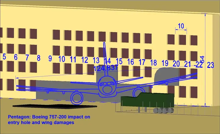
If a 757-200 impacted the Pentagon, column 21 must be hardly damaged like the actual column 19. Figure 5 shows such an impact of 757-200 on column 14. The whole damage must span from column 6 to column 22. But there is no such damage on the wall of the Pentagon.
Debris of 757-200 visible in official reports
In figure WC21, we see the image of a combustor case and high-pressure fan. A more precise image is visible in figure 6. Closer analysis of the combustor case shows that all flange connection bolts are removed. They are not cut, they are rotated and dismounted; the bolt holes are empty. These bolts were removed before the impact. So, this part was not operating in the plane. It was not part of the engine of the plane. If it was actually found in the Pentagon, it was planted inside the 737-400 plane.
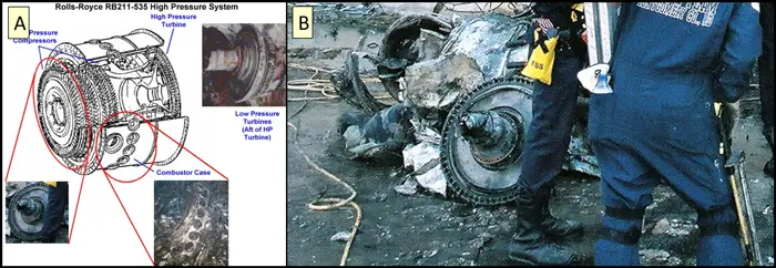
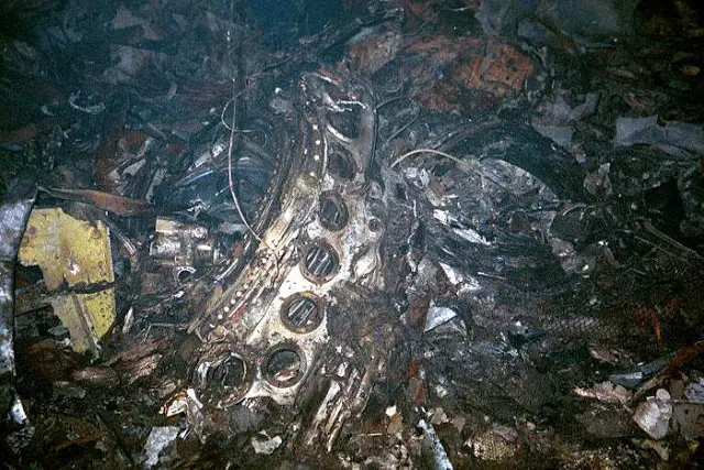
The same is applicable for the high-pressure fan wheel. Such a fan wheel is deeply inside the engine. At impact time, it cannot get out of the engine with keeping the small fan blades intact as it is visible. This wheel was planted inside the 737-400 plane.
In figure WC22, Wayne Coste shows the wheels and arm of a 757-200 landing gear. The official report and the images show that these wheels and the landing arm were found near the exit hole in ring C. That is straight in front of the entry hole. As the plane rotated during the impact, and these parts were detached from the plane when they impacted the Pentagon wall, the movement of these parts could not be straight forward. It was more perpendicular to the façade. Even if they continue their way, they will not reach the exit hole. So, these parts were not the ones of the impacting plane. They were planted inside the 737-400 plane.
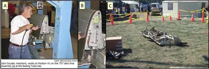
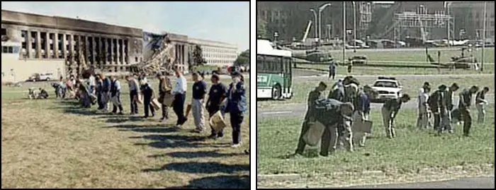
In figure WC25, Wayne Coste shows a leading slat of a 757 aircraft staying on the lawn. With the surrounding persons and workers, we can easily say this picture is dated from several days after the impact of the plane. But the lawn was fully cleared on the day of the attack; figure 7 shows aligned people clearing the lawn for even smallest pieces. Such people looking for the smallest pieces could not let this huge leading slat for several days, and without any smaller pieces around that should exist in such an impact. There could not be any such debris remaining on the lawn. Except if it is brought and put there days after the impact for purpose of creating faked evidence for the presence of a 757. That is definitely not evidence.
In figure WC26, Wayne Coste shows the uplifted second floor slab. He refers to his February 2024 paper in the Debated Topics Forum and claims that this was made by mechanical damage. He explains the reason by saying “the source of the damage as the kinetic energy of the rapidly rotating jet engines [10] which were forced to redirect their motion chaotically due to torques from multiple impacts with columns and the dynamic effects of gyroscopic precession.“
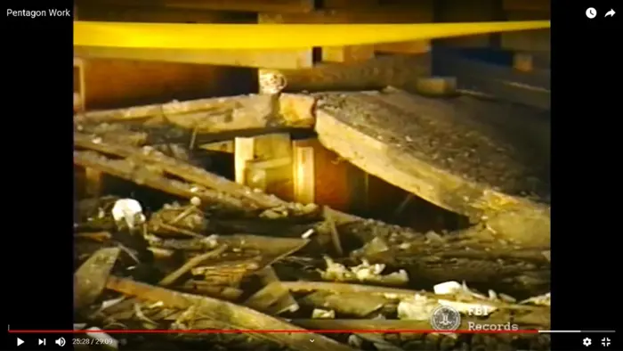
In such a slab uplifting, all damages are mechanical. But nothing proves this uplifting was made by mechanical impact of plane parts. The claimed dynamic effect of rapidly rotating gyroscope is mainly keeping the movement of the object straight. That’s why it is used in gun bullets. In all modern guns, the fired bullet is made rotating in order to keep its movement as straight as possible. In such case imagining that the object will abruptly change direction and uplift the slab is totally wrong. Even in such rotation, the remaining force after the direction change is very small compared to the forward inertial force.
In such an impact, when the engine is impacted to the façade, the engine is damaged. As the gap in the internal wheels and blades is very small, any broken blade or bended wheel will break several parts and stop very quickly the rotation.
With such a mechanical impact, there will be no overpressure reaching the second floor. Then the windows frames of the ring C second floor that are bended outward become impossible to explain. These frames are visible in figure 8 here below and in figure MI15 of my initial document. But Wayne Coste does not speak about these frames. These frames are situated in front of this uplifted second floor slab. The outward bending on these window frames proves that an overpressure of explosion reached the second floor in this direction.
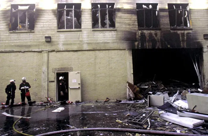
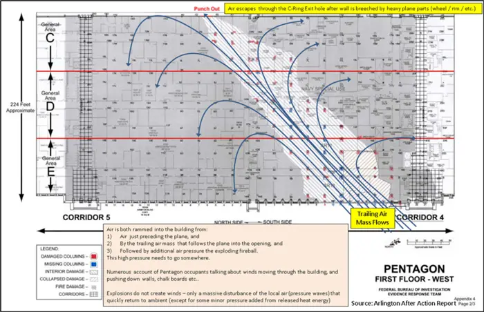
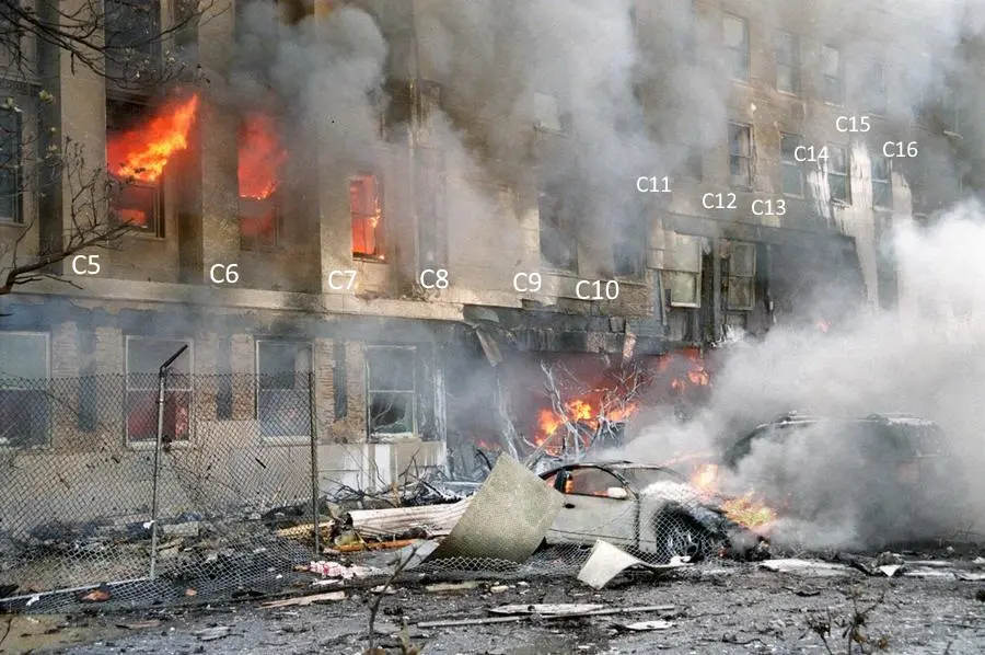
In figure WC28, Wayne Coste claims the roll-up door was damaged by the air entry due to large air entry with the plane. This roll-up door is also visible in figure 8 above. In reality, such a plane mainly creates downward air movement. That’s why an aircraft flies in the air. Even if we imagine an air entry, this air will be stopped by the inner walls preventing it from reaching the roll-up door in ring C first floor. Even if we imagine such air entry, the windows in the outer ring E between columns 5 and 8 would not be damaged (see figure 9 below). Especially because they were renewed with stronger glasses. But they are destroyed. That destruction is the consequence of the explosion that happened below the uplifted second floor slab.
Wayne Coste claims there was no explosion: “Explosives of a significant scale would be very unlikely because Major David King was near the location of this alleged explosion and yet was not injured by what would have been a massive explosion.” We know by the second of the 5 released images, there was an explosion. April Gallop said she heard “an explosion”. We cannot deny the presence of an explosion. And this uplifted slab is the consequence of this explosion. Saying it was “a massive explosion” is meaningless.
From his testimony, we know that Major David King was in room 1 Delta 518. Floor 1, ring D corridor 5 begins north of column 1. The figure 7.9 of ASCE report shows that only one corner room is damaged in this section. So, David King was next to the damaged area, but out of it, reducing the effect of the explosion on him.
Conclusions
Except for figure 9, my June 2024 paper remains fully consistent and valid. For figure 9, I redrew it with better precision in figure 1 and 2 above. These new figures are referred to measurement made with Google earth permitting anybody to check the reference dimension.
The most precise measurement of the wingspan of the plane is based on the damage span from the impact column 14 to the last damaged column 20 on the right side. That gives a wingspan of 95ft. This is fully consistent with the impact of a 737-400.
But by expanding the damage to column 21, Wayne Coste tries to remove the meaning of this right side damage span. The wingtip of a 757-200 should strongly damage the column 21. The images show no impact of any wing section between C20 and C21. The claim of an impact of 757-200 must therefore be definitely rejected.
All other evidence given by Wayne Coste are either false or meaningless.
Appendices
In order to make clearer comments, I directly commented the pdf files of Wayne Coste. These files are attached to this document.
- Coste-Wayne-rebuttal-to-identification-of-the-plane-model-that-impacted-the-pentagon_coste_jan-2025-Commented.pdf : The main rebuttal document of Wayne Coste with my comments included as annotations.