Editor’s Note: Response papers are welcome through October 28, 2024.
The purpose of this document is the identification of the plane model that hit the Pentagon on 9/11/2001. The official story claims that the aircraft of Flight AA77, a Boeing 757-200, impacted the Pentagon. On 8 March 2002, CNN published 5 images of CCTV camera. In January 2003, these images were included in the official report of American Society of Civil Engineers, ASCE, on the Pentagon, Figures 3.3 to 3.7 but without date and time. The first two images are the most important.
Figure 1 shows the first, and Figure 2 the second of these images. In the first image, we see the tail of the plane. The fuselage is hidden behind a box. The second image shows the explosion which is much hotter than kerosene explosion of the twin towers. In the following three images we see the explosion progress and cool down. Nothing permits to identify the aircraft.

The five images are dated of September 12, not 11. Time has 8 hours difference. The dates and times are written in the same font as the identification of the image (“plane” and “impact“) which obviously could not be on the original image. These images were modified. That’s probably why ASCE report did not include date, time and description texts. But the images are identical.
Figures 3 and 4 show two pictures of people clearing the lawn from all debris. One shows people walking in line on the grass, occupied to collect all remaining debris on the Pentagon lawn. The other one shows people, in white shirt and tie, picking up debris and hurry to gather them. That can be considered as normal, gathering all evidence of a crime scene. But it also means that there is a will to hide all images and evidence of this plane.


Testimonies of eyewitnesses
In 2006, I analysed all testimonies regarding the Pentagon attack. Apart from the crew of a military C130 aircraft, more than hundred testimonies were released. Many saw a civilian aircraft fly and hit the Pentagon. Ten of them speak about a 757 or alleged to be identified thereafter. Many are military persons or working in the Pentagon.
Only one civilian pilot, Tim Timmerman, who was near the Pentagon, identifies a B757. Later he became Donald Timmerman, and Hugh Timmerman. His live testimony on CNN is here. https://www.youtube.com/watch?v=W0dwQmOLyqk
Here is an extract from this testimony to CNN on 9/11, 2001 13:46 ET: “… And then it came out, and I saw it hit right in front of — it didn’t appear to crash into the building; most of the energy was dissipated in hitting the ground, but I saw the nose break up, I saw the wings fly forward, and then the conflagration engulfed everything in flames. It was horrible… It was a Boeing 757, American Airlines, no question.” But the analysis of all images showed there is no evidence that the plane hit the ground. We can state that Timmerman made a false testimony.
Timmerman is presented as a roommate of Dawn Vignola. In a video, Dawn testifies live on a TV channel, and during the testimony we hear a person whistle the right words to say and she repeats them immediately. She also says that her roommate works in aviation. https://www.youtube.com/watch?v=jh2iFhTYX5s We can imagine that Timmerman was telling her what she must say. These two testimonies look like theatre.
Another civilian, Terry Morin, professional in aviation, says: “It looked like a 737 and I so reported to authorities.” https://web.archive.org/web/20011122065302/http://www.coping.org/911/survivor/pentagon.htm
In all these testimonies, there are enough people who could make the difference between a civilian airliner and military aircraft or missile or drone. But recognizing two different civil aircraft models within a few seconds of visibility of the aircraft is not an easy task, even for experienced people. In preparation of these attacks, the perpetrators can imagine using a civilian plane that looks like the B757. It is impossible to use a missile or military aircraft or drone; we can reject such claims.
Analysis of the available evidence
Figure 5 (similar to Figure 3.8 of ASCE report) shows the left side of the entry hole. We can see the entry hole between columns 13 and 15. The last damaged is column 8.

Figure 6 (similar to Figure 3.9 of ASCE report) shows the right side of the entry hole in the façade after the impact and before the collapse of that part of the facade. We can see the entry hole in the left of the image centre, where the fire continues to burn. On the right of the image centre, we can see the last damaged column 20.
ASCE report on the Pentagon gives many pictures of the damage on the facade and inside the building. From all these pictures we can draw the following conclusions:
– There is no single image of passengers or aircraft seats inside the Pentagon. That makes possible another aircraft impact. That also suggest this other aircraft was empty of seats and passengers.
– The nose of the plane hit the column 14 of the west facade of the Pentagon. This is the opposite side to the main entry door. The bigger damage on C13 than C15 suggest that the impact was not perfectly on C14, but it was a little shifted toward C13.
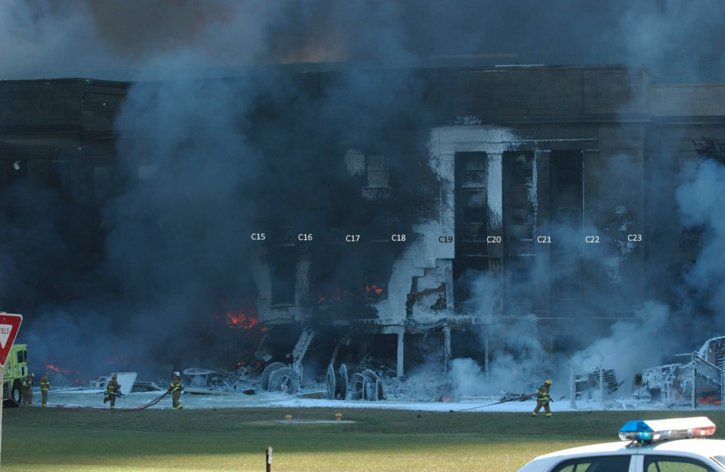
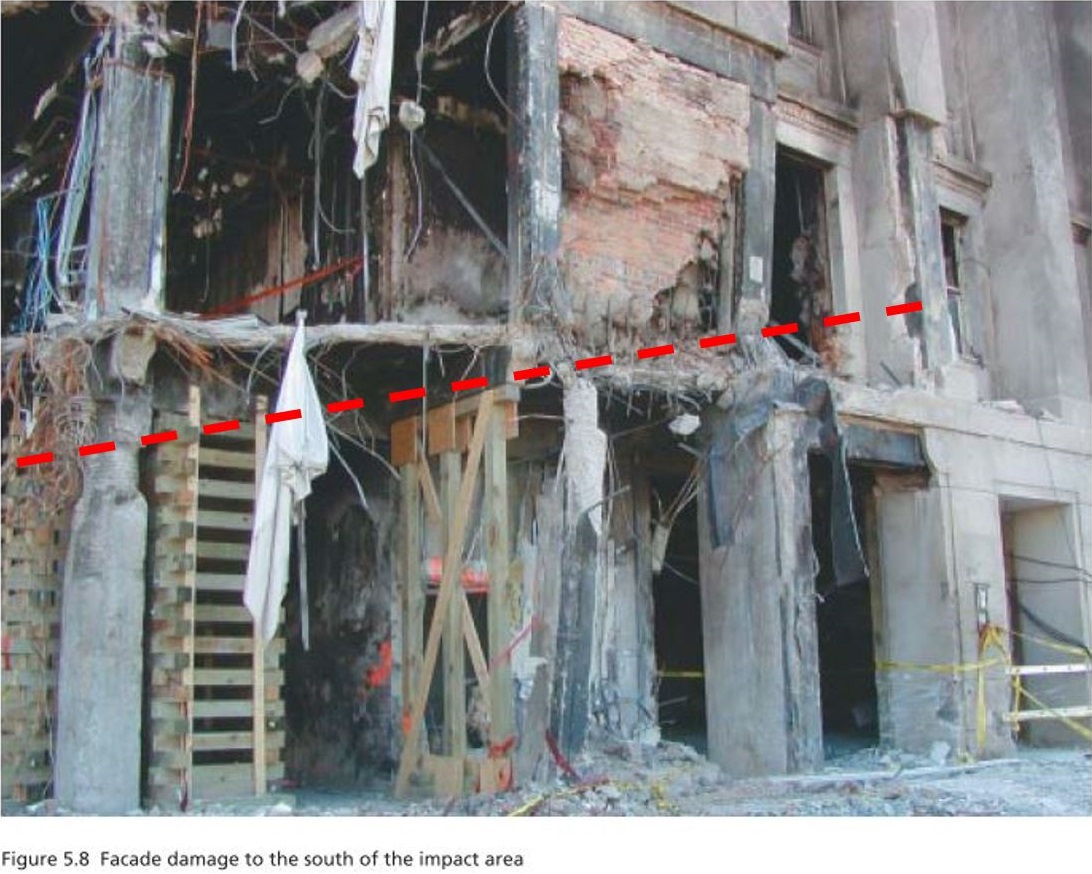
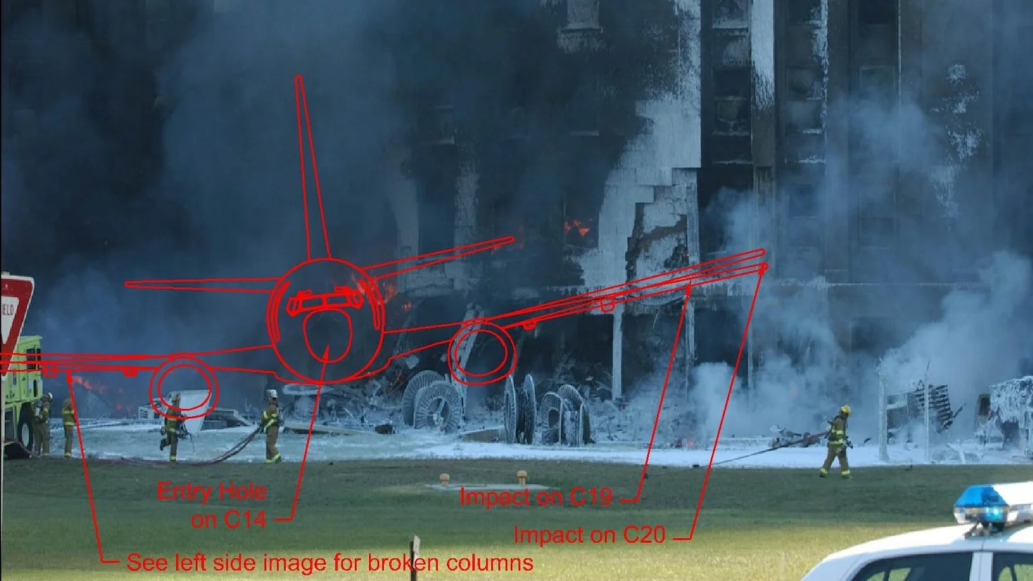
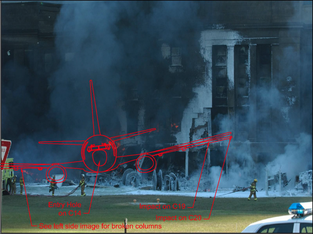
– The extremity of the right wing hit the column 20 at the level of the second floor, leaving straight traces of a wing on columns 19 and 18. Figure 7 (Figure 5.8 of ASCE report) shows a close image of damage on C18, C19 and C20. The damage is consistent with the impact of a right wing of a commercial airliner. The traces of the wing go from C20 on second floor down to the entry hole on first floor. This wing also destroyed the columns 15, 16 and 17. The pending concrete parts at the places of these columns in Figure 6 are collapsed horizontal parts of the second-floor level.
Figure 8 shows these traces with the image of an aircraft. The wings of the plane in this image were doubled. The upper wing represents the position of the wing in flight which is slightly raised, although its curve is not perfectly represented.
– Left wing hit and destroyed columns 13, 12, 11, and 10 at about 2 meters above the ground. It heavily damaged column 9 leaving only concrete reinforcement in curved position. Finally, it damaged the surface of the column 8.
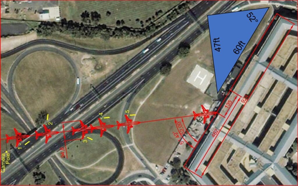
– Figure 9 shows the approach angle of the aircraft toward the building. This angle is about 52°. Taking into account the impact with the generator which turned the plane a little to the right, the angle becomes a little smaller. This angle was measured on basis of the light poles destroyed before the impact and the direction of damages inside the building.
– Only light pole 2 fell almost perpendicular to the path of the aircraft. It had to be hit on the lamp situated out of its centre. The impact rotated the light pole that fell out of the road. This impact with the light pole 2 gives us a good precision about the position of the aircraft. If the plane wingspan was bigger, the right wing would also hit the surveillance camera pole to the right of pole 1.
– Pole 1 impact is lower than the impact to pole 2. This implies that the wings of the plane were lower on the right side, and higher on the left side. But at impact time, it is the opposite; the left wing is lower. This is not consistent with the control by a human pilot who will not change direction within so short time. That suggests the planes were controlled by automated closed loop guidance systems that continued to correct up to the impact, balancing left to right and right to left. This system is similar or upgraded control system of cruise missiles, such as Tomahawk.
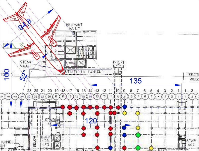
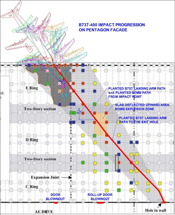
– From the impact of the extremity of the right wing to column 20 of the façade, the aircraft started to rotate, slowing the right side and speeding the left side. This rotation reduced damages on the right side, and increased damages on the left side. Biggest difference is visible when comparing the damages of columns 18, 19 with columns 9, 10. Damage to columns 18 and 19 on the right side are much smaller than those in columns 9 and 10 on the left side, although the second-floor slab situated at impact level on column 18 also reduced the damage on this column. Figure 17 shows the progression of the impact.
Measurement and calculation of the aircraft wingspan
The entry hole is located on the column 14, the last damaged column is number 20. Between these two points representing the damage made by the right half of the plane, there are 6 columns bays. This damage on the right side is the most precise one, because it was made before the plane began to rotate. The distance between two columns is 10 feet (3 meters). The damage on the right side spans over 6 columns, this makes 60 feet. Converted into the perpendicular to the plane, it is 60 x sin (52 °) = 47 feet. This is half wingspan of the aircraft. Double, 2 x 47 = 94 feet (29 meters), is the wingspan of the aircraft. C13 is more damaged than C15 showing the impact was on C14 but a little toward C13. So, the precision is roughly estimated to -0/+4 ft.
This information is very reliable. Because at the speed of the plane, the slightest impact on the facade, even with plastic material, makes traces. Before the right wing touched the façade of the building the plane remains in its initial direction of 52 °.
The wingspan of B757 is 125 feet (38 meters). That does not match the damage on the façade. The official ASCE report considers the entire damage from column 8 to column 20 and uses a false angle “of approximately 42 degrees to the normal to the face of the building“, that gives 48 degrees from the façade. There is 4 degrees difference. On page 35, they calculate the wingspan as 90 feet. This report is so imprecise that we consider 94 feet.
Official explanation of wingspan difference
The difference between 125 and 94 is obviously inconsistent. To explain this fact, the authors of ASCE report wrote in paragraph 6.1 on page 35: “In any event, the evidence suggests that tips of both wings did not make direct contact with the façade of the building and that portions of the wings might have been separated from the fuselage before the aircraft struck the building. This is consistent with eyewitness statements that the right wing struck a large generator before the aircraft struck the building and the left engine struck a ground level, external vent structure. It is possible that these impacts, which occurred not more than 100 ft before the nose of the aircraft struck the building, may have damaged the wings … “. Beautiful work to justify the false. But this report does not stop there. It is full of inconsistencies and falsehoods.
Although the impact of the right engine, not the wing, to the generator is visible, it cannot in any way explain the break of the wing tip. For the left engine, there is no evidence explaining that it hit the wall on the ground. There is a notch in the wall visible in Figure 10.

There is a satellite picture of this area dated from September 7 in which 6 cable spools were between the generator and the ventilation structure. These are the 6 black dots visible in the background image of the Figure 9. In the pictures made after the attack, including Figures 5 and 9, two spools are between the ventilation structure and the façade of the building. This notch in the ventilation wall was most probably made by the cable spool indicated in Figure 10. This spool has been pushed by the plane and crossed the ventilation wall to become closer to the façade of the Pentagon.
The notch in this wall cannot be made by the left engine, because there is no trace on the ground before and after the wall. This break is clear to the ground. The engine cover would touch the ground before breaking the wall at the ground.
In addition, the level difference between the wall and the damage to the generator requires an excessive oblique angle of the plane. Figure 15 shows this impossible position of the aircraft. In this case, the right wing is placed too high above the damage on the façade, and the left wing too low. To avoid having to explain this fact, 3D model included in the page 35 of ASCE report does not represent the generator. Also, this image could be at least 2 times larger to have better visibility.
We can say that there is no reason why both wings have their tips shortened by 15 feet (4.5 meters). The only remaining explanation is that the plane is not a 757. In this case what model is this plane?
Identification of the actual plane model
Hundreds of witnesses cannot be wrong, they may easily make the difference between a civilian airliner and military aircraft or missile or drone. But recognize the exact model of the aircraft within few seconds is not easy. We can imagine a different model of civil aircraft. Models 737-300, 400 and 500 have a wingspan of 94ft 9in (28.88 meters). The 737-400 is the longest of these three models (119ft 7in), although much shorter than B757-200 (155ft 3in). This model, 737-400 is the most consistent aircraft with the evidence and eyewitnesses’ testimonies.
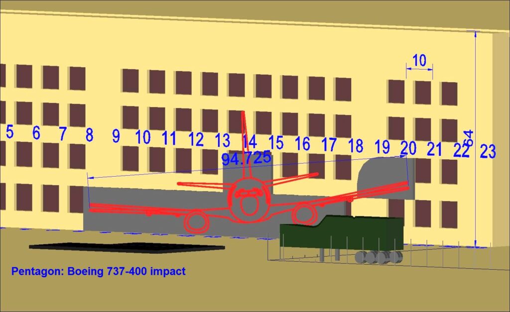
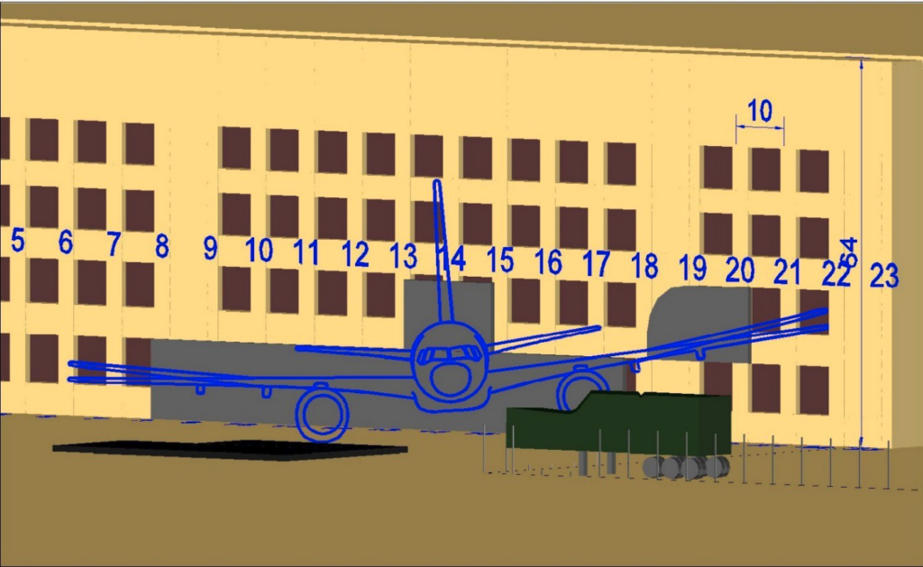
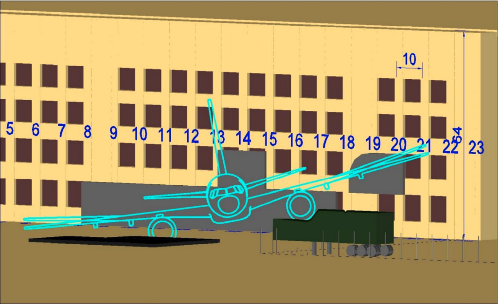
Figures 11 and 12 show scaled 2D and 3D models of the impact using a 737-400. Everything fits perfectly with this aircraft model.
It’s important to notice that in the 3D models used in figure 12, 14 and 15, the plane is at about 100ft from the façade, the image is flat (not perspective), and the smallest direction change of about 0.5 degrees moves everything in the image. In other words, the Figure 12 is a very precise 3D model of the impact.
Let’s remember that the aircraft model Boeing 737 was quoted by a civilian eyewitness, Terry Morin who is experienced in aviation. He said, “It looked like a 737 and I so reported to authorities“. He felt he made a mistake when authorities said the plane is a 757. But he was one of the few persons being able to identify the aircraft.
Figures 14 and 15 are 3D models of the impact of 757-200 on the damages of the facade. If the generator is aligned, the hole is not and vice versa. Wings always exceed the damage. Always the left engine touches the ground but there is no single trace of such impact on the ground.
Analysis of other evidence given in ASCE report
In ASCE report “Figure 3.17 Fatalities found in first floor”, see Figure 13, the black square near the exit hole in ring C shows the position of “Flight data recorder and landing gear”. This position is straight forward in the path of the aircraft. But these parts are strongly tied to the aircraft. They cannot be separated from the aircraft at the beginning of the impact where the weak nose does not create much deceleration. Later, during the progression of the impact, the aircraft rotated leftward. See figure 17 for this rotation. When these parts detached from the aircraft, their direction was changed. They cannot go straight forward and they cannot reach the exit hole situated straight in the aircraft approach direction. For making these parts continue their way straight forward as shown in the ASCE report, these parts must be planted inside the aircraft with weak connections, such as used for transportation. That means these parts were planted inside the empty aircraft; they were detached from the aircraft immediately at impact time and continued their way straight toward the exit hole. These parts are not parts of the aircraft that impacted the Pentagon.

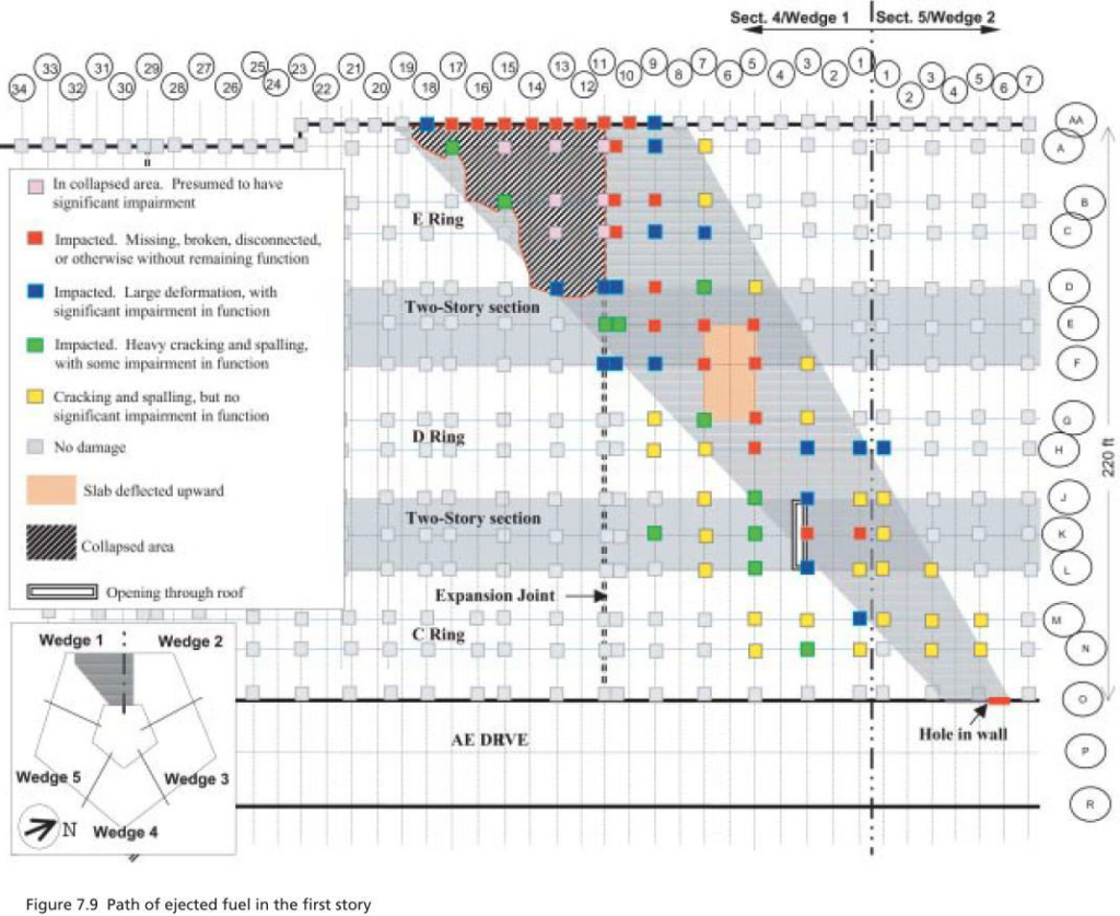
In ASCE report “Figure 7.9 Path of ejected fuel in the first story”, see Figure 16, an orange area is drawn between columns E5 and G7. Figure 17 is made on basis of this figure 7.9 of ASCE report. The orange area is identified as “Slab deflected upward”.
In “Figure 5.27 Breached second-floor slab”, see figure 18, this slab is shown from the second floor. This upward deflection is the consequence of an overpressure under this area. Such an overpressure can only happen in case of explosion under this area.
That means there was also a bomb inside the aircraft. This bomb also continued it way straight forward and exploded when it reached this orange area where the slab deflected upward. The overpressure of this explosion spread in all direction in the first floor destroying the roll-up door in ring C and windows between columns 4 and 8 in ring E. When reached the second floor, the overpressure was much reduced and directed inward. That’s why it bended the window frames and broken the glasses on ring C between columns 5 and 10 as visible in Figure 19.


Conclusions
The most precise measurement of the wingspan of the plane that impacted the Pentagon gave the wingspan of 94ft (tolerance -0/+4ft). There is no doubt about this wingspan. And that is consistent with a Boeing 737-400 aircraft with 95ft wingspan. The damages on the light poles, on the generator trailer, on the fence, on the ventilation wall, on the facade, on the facade columns, inside the building, … are all consistent with the impact of that 737-400 plane.
The plane was empty of its seats and passengers. It was rigged with a 757-200 landing arm, a prerecorded Flight Data Recorder and a bomb. These parts continued their movement straight toward the exit hole in ring C. The landing arm and the FDR were found near this exit hole. The bomb exploded in ring D between C5 and C7, deflecting the slab upward. This expelled outward the window frames between columns C4 and C8 in ring E. In ring C, this explosion destroyed a roll-up door between C5 and C7 in first floor and window frames between C5 and C10 in second floor. This explosion is visible in Figures 3.4 to 3.7 of ASCE report.
That means the Perpetrators changed the plane from 757-200 to 737-400 between 8:54 deviation of the plane and 9:38 impact to the Pentagon. The question is: Why the perpetrators changed the plane and how? This will be the subject of a forthcoming document with wider scope.

