Editor’s Note: This paper is a response to the October 2024 paper by David Chandler and Wayne Coste. Chandler and Coste’s October 2024 paper was a reply to Arena’s May 2024 paper, which was a response to Chandler and Coste’s original October 2023 paper, the first in this thread. We encourage readers to read all four papers in the thread.
Thank you to IC911 editors for allowing this delayed response.
My stepson, Xander Allen Thorstad, Lance Corporal USMC, died in a tragic accident in July 2024. Our world has been shattered, and the grief is still grave. Mustering this reply has been difficult, to say the least.
Introduction
Delving into the damage at the Pentagon allows us to deconstruct mistakes and dispatch misunderstandings.
In this second reply to “Large Plane Impact Damage to the Wall of the Pentagon and Adjacent Objects” (hereafter, LPI), I will revisit the evidence, refine the analysis, and show that my prior findings are sustainable. “No large aircraft hit the Pentagon in 2001.”
In adopting the LPI authors’ convention of using “XA” and “LPI” to refer to prior figures and the papers themselves, I shall also add a numeral after the abbreviations, to indicate which paper I am referring to: LPI1 or LPI2, and XA1. Figures found within this document will be referenced in bold type.
In this reply, rather than focus exclusively on subjective interpretations of the appearance of evidence, I will also utilize computational analysis of the energies involved. My mathematical calculations consider an impacting airplane to weigh 180,000 pounds (lbs) and to have been travelling at 530 miles per hour (mph), which are reasonable and favorable assumptions based on the information given to us by official sources. These calculations definitively demonstrate that my overarching assessments are accurate and serve as a call for further analysis and action.
Withdrawal of Claim
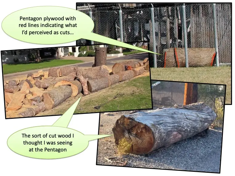
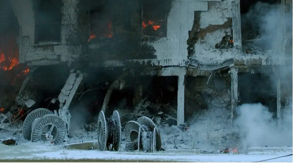
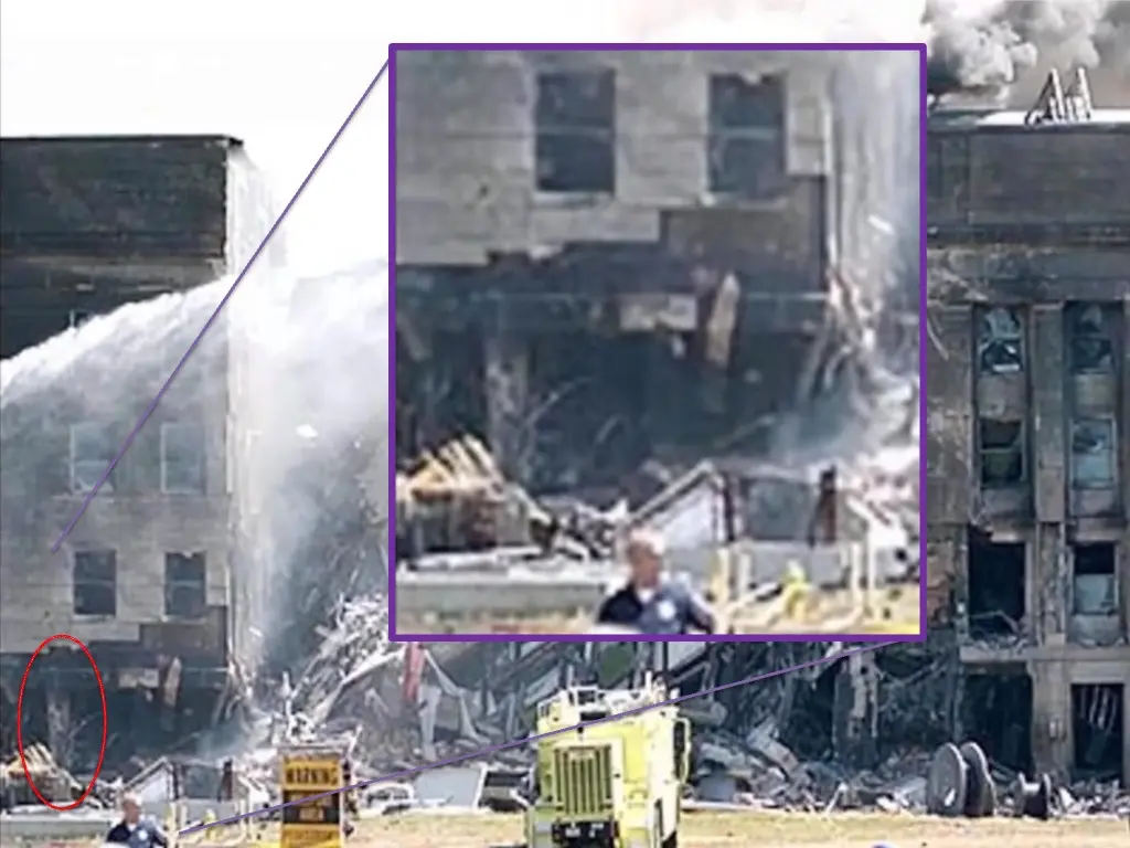
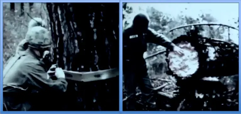
Publishing a reply within the specified time constraints of an online debate can be challenging. I regret that, in my haste to produce a reply to LPI1, I made a significant mistake in XA1. In a momentary lapse, I failed to appreciate the scale of the lumber sheet near the generator fence (XA1 Fig. 16). I saw the sheet as a cut tree trunk (Fig. 1). But clearly it was much too large to be a portion of the Column 16 tree and is plainly plywood when shown from other angles, as was done in LPI2. I hereby withdraw the claim that the tree appeared to be saw-cut. Mea culpa!
Progress and Proof
I’d take that mistake in a moment in exchange for all we’ve learned in the process. Chiefly, we learned of Column 18’s pristine pre-collapse condition in XA1. This critical finding is a critical contradiction to the official story, yet it was not addressed in LPI2. Yes, the authors provided a new graphic which showed the column’s pre- and post-collapse positions (see LPI2 Fig. 2), but its position was not the key issue. The southward position had already been explained in XA1 as mechanical breakage. Imperatively, XA1 sounded the alarm regarding the fully intact 18th column pre-collapse. That alarm is still ringing.
Column 18 was composed of up to 4,000 pounds per square inch (psi) rebar-reinforced concrete and had an approximately 3-inch-thick limestone cladding. Behind it lay 6-inch-thick concrete flooring. That floor slab may have resisted some of any force exerted against it, but it would have also experienced edge-on-edge shattering from collision with a Boeing 757 wing at 530 mph. That same wing would have decimated the 18th column—a physics phenomenon that LPI2 ignored. Let’s fly this point home for good.
We can approximate the limestone cladding to have had about 7250 psi of compressive strength and even less tensile strength. This 7250 psi figure is, if anything, an overestimation. It is based on both the highest-quality cladding available from the quarries used during construction of the Pentagon (September 11, 1941, to January 15, 1943) and the 60 years of weathering it had undergone (up to September 11, 2001) in an urban environment. Similarly, we can approximate the reinforced column to have had a compressive strength of about 4000 psi, with many sources citing a significantly lower value based on standards of the early 1940s. 4000 psi is a generous assessment. And even though the rebar inside the column had a much higher yield strength, the dynamic loading of a large plane’s impact would have reduced the effective strength of the concrete to about 3000 psi.
It would take less than 5 megajoules (a measurement of energy—MJ for short) to crush the cladding and less than 10 MJ to destroy the column. The wing of a 757 travelling at 530 mph would have delivered well over 100 MJ impact energy in the right midwing alone. 100 MJ of energy would have obliterated the limestone cladding, shredded the column, and shattered the slab’s edge. Yet there it was, an intact Column 18 (XA1 Fig. 8). 100 MJ vs 10 MJ is a massive mathematical mismatch. Thus, the critical finding that no 757 wing impacted Column 18 is empirically defended. XA1’s conclusions stand. If the right wing was intact, LPI’s hypothesis is nullified. If it was not intact, where did it go?
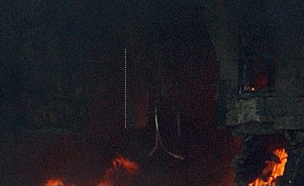
I ask the radiologists in the room to closely examine Fig. 2 above and then infer what may have affected the body of the building. Concrete columns fail at 1-to-2 MJ of impact energy and are decimated at 10 MJ. Did an airplane wing with hundreds of megajoules of energy transect those columns? Since the energy enigma and damage disparity definitively rule out wing collision, what is your differential diagnosis?
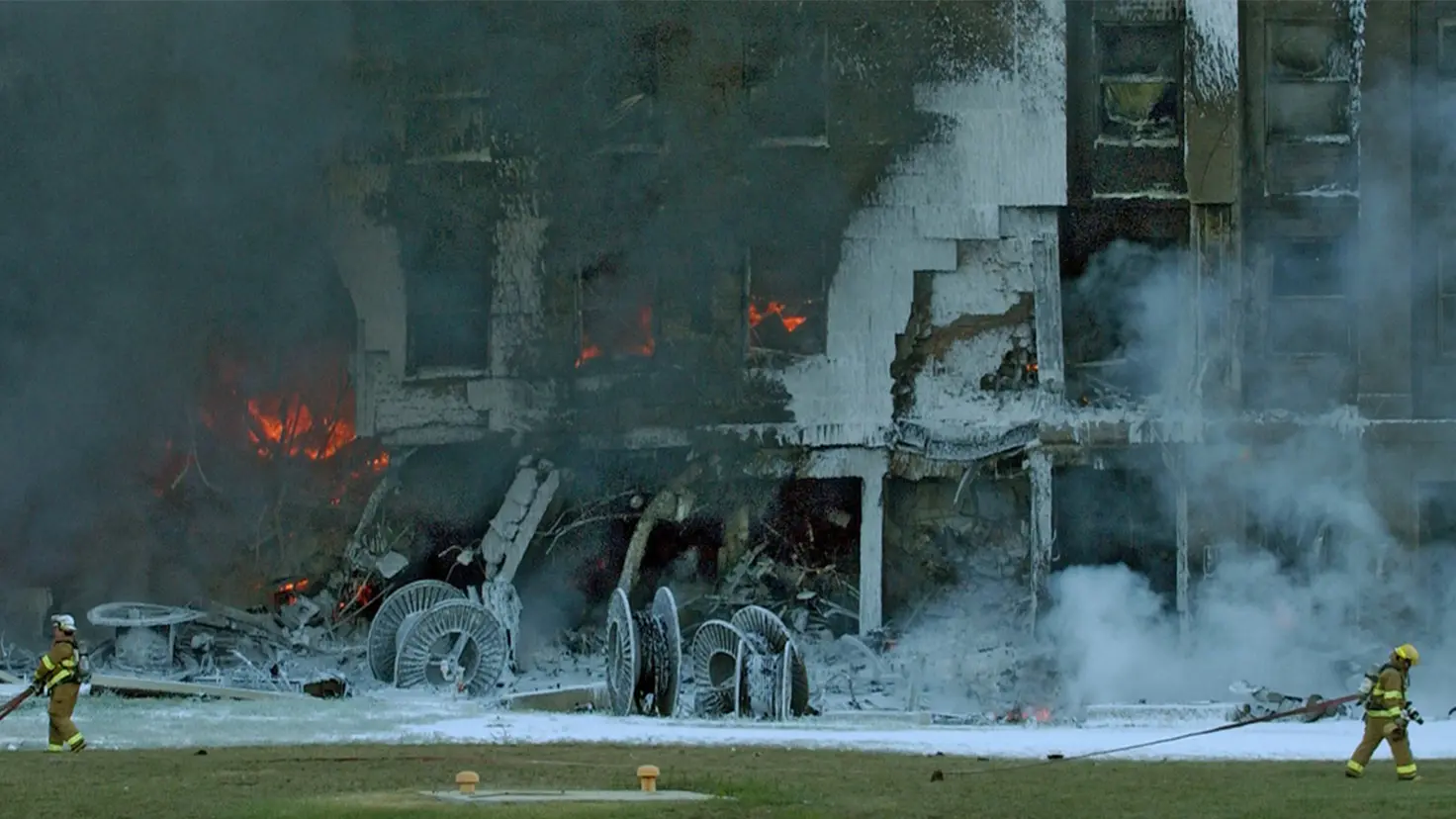
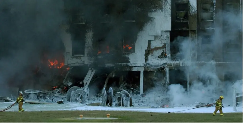
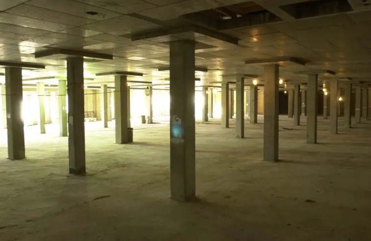
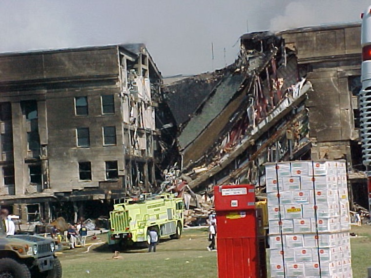
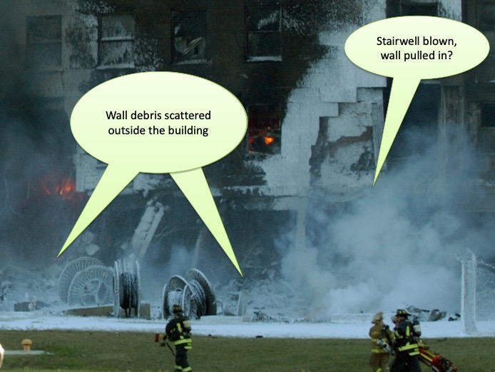
Please take a closer look at Fig. 3. Do you see a 757 inside that portion of the building? No? Neither did early witnesses—notably Jamie McIntyre, who reported seeing no large plane parts outside the building and did not report seeing any parts inside the building.
There were no wing sections or tail sections visible inside the façade or outside the building that day. Only a blown-up, flaming exterior ring of ourPentagon could be seen.
Damage Assessments
There are a lot of reasons to suspect foul play at the site that morning. Thierry Meyssan’s depiction of a small hole in the second story is still one of them (see LPI1 Fig. 6). For instance, in the picture he published, where is the damage from the tail of a large aircraft? A 757’s tail would have extended over 40 feet (ft) into the air, well above the second story. On the third story, the tail would have gouged its way through the E Ring and toward the D Ring. But we do not see such damage anywhere in Fig. 4 (below). Thus, the radius of damage above the 2nd floor is inconsistent with a 757 strike at any speed, let alone at 530 mph.
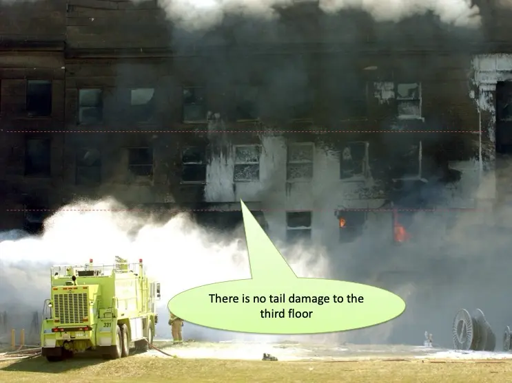
However, let’s consider a hypothetical 3rd-floor collision. A 757’s tail weighs over 5,000 lbs. Factoring in attenuation of forces from initial fuselage collision, the tail still reaches the façade at over 500 mph. That’s over 100 MJ of kinetic energy (KE) in the tail alone. To put this into perspective, a semi-trailer truck delivers less than 5 MJ in a 60-mph collision. Would a large truck driving into the Pentagon wall at 60 mph leave intact limestone cladding in its wake? No. The cladding would be shattered, and after a collision with nearly 20 times that energy, everything behind the limestone would be cleaved. This should have left a fissure in the 3rd-floor façade. So, instead of having images showing impact by a “tall tail,” we now have tell-tale signs that we’ve all been told a “tall tale.”
Whether on the 14th column line or the 12th column line, the 3rd floor should have been destroyed. To overcome the lack of damage seen above the second-story aperture, LPI1 asserts that yaw induced from a generator collision rotated the airplane’s tail to its port side. They say that evidence of a more northern tail impact is seen in LPI1 Fig. 22. And they insist that the damage seen on the 12th column line on the 2nd floor must have been from the tail. Yet in that image, there is—to repeat—no damage to the 3rd floor! LPI1 authors say “the tail was dragged in.” But is that physically feasible?
If an aircraft hit the generator, yaw would be induced by both drag and asymmetric thrust. But would that yaw be meaningful in the short distance travelled before the alleged E Ring impact? No, it would not. Fortunately, we can quantify the conundrum, and we will do just that in the next paragraph.
Foremost, a 180,000-lb Boeing flying at 777 feet/second (ft/s) has more than 2000 MJ of energy. It would only minimally yaw when carving through the corner of a stationary 40,000-lb generator trailer with sub-second contact time. Consider that 2000 MJ of 757 vs maybe 10 MJ of energy loss from upper generator impact and deformation would rotate the massive jet merely a few degrees. Even if there were a total loss of thrust from right-engine impact, the tail wouldn’t have rotated into Column 12 in the first place. In the second place, the tail would have destroyed the 3rd floor. In the third place, the tail wouldn’t have been “dragged in.”
I hope to lift the reader out of LPI’s misunderstanding, because the notion that the tail, or wings for that matter, could be “dragged in” is just not true. Aluminum wings and tails shear at those speeds. The 7075-T6 aluminum spars have yield strengths of 72,500 psi, and the concrete slabs and columns would act like blades upon them. The spars were not unbreakable ropes that would wind their way around concrete columns, pulled after the runaway fuselage. Instead, they would shear off the body of the aircraft from the dynamic impact and at those speeds punch through the façade themselves.
Focusing now on the second story, I’ll introduce a style of column labeling that adds a trailing letter denoting the floor: A=1st floor, B=2nd floor, C=3rd floor, etc. So, Column 14AA is the outermost column on the 1st floor, and Column 14AAB is the outermost column on the 2nd floor.
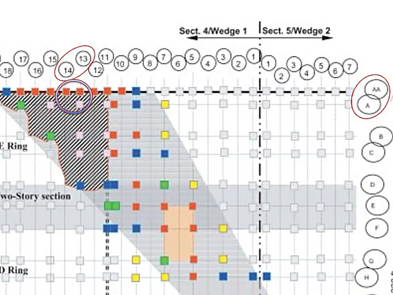
The captions in XA1 Figs. 12–14 identified an intact column in the second-story aperture but inadvertently referred to it as Column 14 in XA1 Fig. 13. (In retrospect, the column I was calling attention to in XA1 appears to actually be Column 13AB.) The location of Column 14AAB in relation to Column 13AB is delineated in Fig. 5 below.
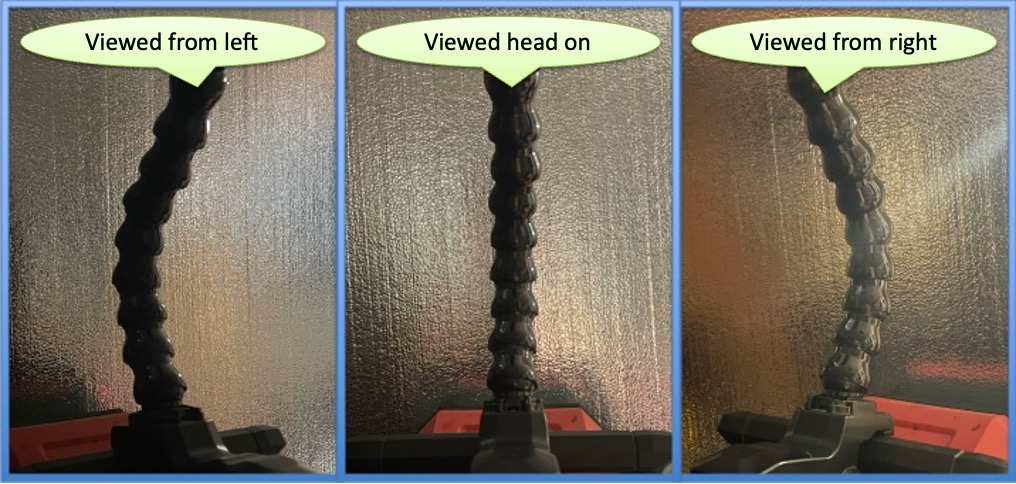
LPI2 replied to XA1 by saying that the column was bent in the direction of plane travel. LPI2 Fig. 4 appears to show Column 14AAB (second-story nomenclature) pushed toward the north. With a refined review, I discern that Column 14AAB may indeed be pushed into the building, but it’s dark and also appears to be pushed toward the south in some images, as shown in Fig. 6.
How can this be? If Column 14AAB looks bent to the north when viewed from the north (as shown in LPI2 Fig. 4) but looks bent to the south when viewed from the south, that means it’s actually bent more toward the east. This is akin to the “leaning tower illusion,” only here we can call it the “bowed column illusion.”
Column 14AAB was bent directly inward. That means the column was not bent in the direction of a purported plane on the alleged approach but was bent eastward by some other mechanism. Fig. 7 below demonstrates how a column may be perceived as having varying directional damage depending on the viewer’s vantage point. When an object appears to bow both directions, it’s actually bowed dead ahead.
There is clearly another column behind 14AAB from the vantage point of Ingersoll’s shot. That column is likely 13AB, emphasized in Fig. 8 below. The logic in XA1 holds. Column 13AB is pristine but should not be intact at all, as it was directly in line with a purported plane trajectory (see Fig. 5 above). Column 13AB looks just as unscathed as the regular Pentagon columns shown in Fig. 9. It should not be.
Remnant Column 14AAB’s direction matters, but the fact it’s still there at all matters even more. Let’s consider the language the LPI authors used when they wrote about Column 14AAB. In LPI2 Fig. 3 they noted that the “column appears short due to hanging at significant angle.” By implication, they were saying that the column was actually longer than it looked.
In LPI1 Fig. 10, they rendered a jet passing through Column 14AAB as if the column were a swinging flap. In XA1, I correctly pointed out that the jet rendering should reflect increased height of the top of the fuselage due to the prescribed bank. Testing their logic, a jet would have had to hit this column somewhere along its length. Yet the column dangled by rebar after purportedly being bent backward by a jet.
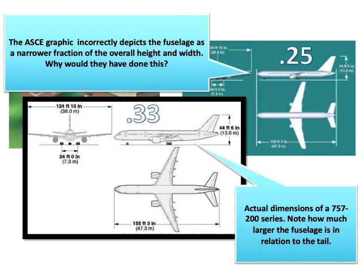
We’re told that the jet was a 757 travelling at 530 mph. The fuselage of the aircraft would easily deliver over 1200 MJ to the 14th column line. The impact energy would obliterate whatever portion of 14AAB was hit (suggested in XA1 Fig. 11 to be about half of its length). The impulse then might bend the remaining portion into the building along the vector of attack. But if Column 14AAB is longer than it appears in the images, according to LPI2 Fig. 3, then it was not struck by a 757. This is because the top of a 757’s fuselage would be too high to leave that much column remaining, hanging or otherwise. Maybe that’s why the American Society of Civil Engineers (ASCE) artificially reduced the fuselage height in the graphic they made for their Pentagon Building Performance Report? That finding was originally sussed out in my “Security Camera Analysis” presentation and is displayed here in Fig. 10 below.
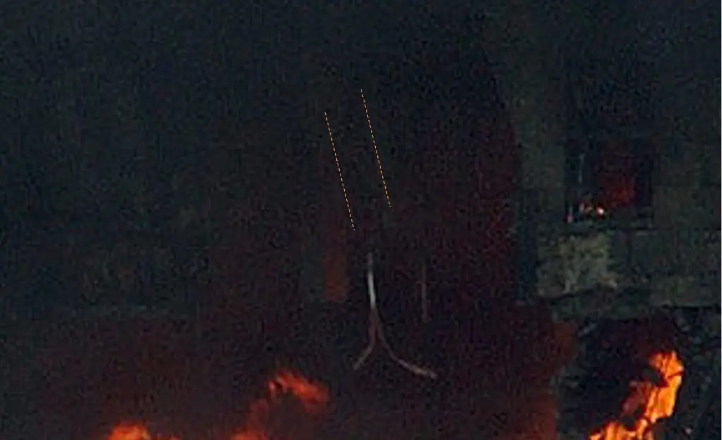
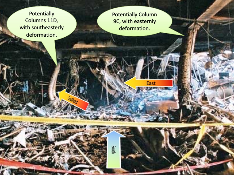
In another instance of columnar illusion, LPI2 attempted to derail XA1’s discovery that Column 9AA wasn’t bent in the correct direction. Let’s take a closer look at Columns 9AA and 9A. They appear bent to the north when viewed from the north, but when viewed head-on, it is clear they are not bent northward. LPI2 Fig. 13 emphasized “maximum deformation” to the northeast, yet Fig. 11 shows Column 9AA appearing very straight, perhaps even bowed to the right (south). Finally, Fig. 12 appears to show Column 9AA bent to the southeast. These new images, pulled from raw video, prove my point. Column 9AA was deformed to the east. The deformation is incompatible with a northeastern vectored kinetic strike. Also let the NTSB photograph in Fig. 13 put the pillar in its place. XA1’s claims do not yield. Column 9AA was not bent in the direction of an impacting airliner along the purported trajectory.
So, columns were bowed, but the tree was not. A felled tree and branches were found north of the initial breach in the E Ring perimeter. I knew of the tree debris before contributing XA1 to the discussion. But, at the time, I’d mistakenly thought a portion of trunk had a saw-cut end, so I’m grateful for the enhanced image provided in LPI2 Fig. 5, which clearly shows that what I assumed was a rippled tree trunk was really blown-apart corrugated trailer material.
LPI2’s correction of XA1’s trunk misinterpretation provided a curious graphic. LPI2 Fig. 7 shows the overlay of a large aircraft, with the apparent intent being to show that the right-wing spar is at the right height to sever the tree. But in Fig. 14 (below), we note that the generator is so far to the right in their image that the alignment they conveyed is incorrect. If their point was solely to consider the possible spar height at E Ring breach, we must not forget the actual alleged impact angle and requisite impact alignment when considering the spools, columns, and damaged façade. The right engine conveyed in LPI2 Fig. 7 needs to be raised to align with the generator, enhancing the required banking angle for retaining wall impact with the bottom of the left engine nacelle.
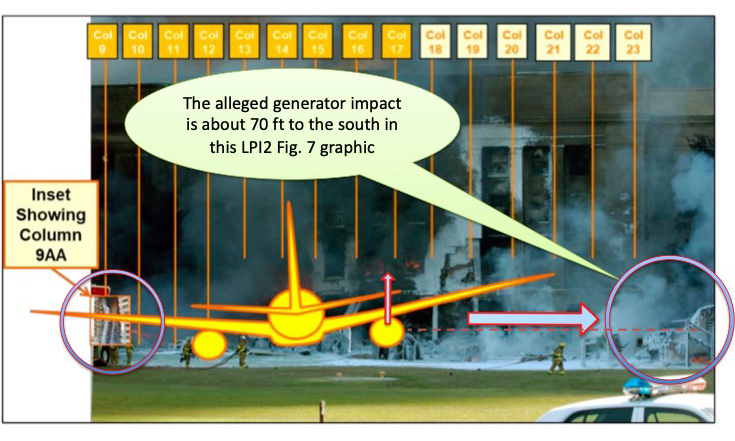
We’ve learned by energy analysis that no plane wing impacted Column 18, therefore no plane wing impacted the tree at Column 16 either. Because LPI2 made a compelling case that the tree was not cut, we must thus consider ordinance. Certainly, explosive ordinance is a plausible mechanism for removing the tree. LPI2 suggested that explosions are always a unified omnidirectional spherical pressure wave. In reality, tuning blast effects to various expansion patterns and vectors is basic explosive engineering. Hollow charges, shaped charges, delayed and secondary charges… explosives can move things in accordance with their design. Any sapper can attest to this. Fig. 15 depicts screen shots from a 1966 US Army demolition video. They are blowing up a tree with an M118 charge. Fifty years later we have products like PRIMASHEET® and DETASHEET®, both of which can move columns and trees with ease. Explosive removal of the tree remains the most likely explanation.
A swath of the argument in XA1 hinged on the left wing sweeping through and damaging more of the building to the north than what actually occurred. Objecting to my point, LPI2 argued that an impacting aircraft would have lost so much energy via resistance points that the left wingtip would have been slurped into the building around pristine Column 8. LPI2 claimed I thought of the E Ring as a “cloud” the plane could just vanish into. Resolution relies on determining the forces involved. The E Ring wall stood with a certain level of resistance, and an impacting airliner would arrive with a certain level of kinetic energy. Let’s quantify the interaction, using favorable factors for the official explanation. We’ll underestimate aircraft impact energies and overestimate wall resistance.
A 757’s wingspan is 124 ft, but we must account for the angle of the alleged approach. By applying trigonometry to the impact angle, we know that its static projection against the wall is only ~100 ft. However, an impacting airliner would also be experiencing forward motion. The left-wing root is ~55 ft aft of the nose, and the wings are swept back by ~28.5 degrees on their leading edge, placing the left wingtip ~88 ft aft of the nose. From the nose’s contact time with Column 14, the left wingtip impact would be delayed by ~0.16 seconds, which also shifts the left wingtip impact location considerably north due to the forward motion. Add that to the static projection of the wings at the prescribed impact angle and we get over 155 ft of wall impact, all the way to Column 6. This concept was correctly shown in XA1 Fig. 1. The question remains: How much energy would there be in that imaginary impact?
Assuming the aircraft’s total mass was about 180,000 lbs and assuming it arrived at the wall at ~530 mph, we’ll start with total kinetic energy of over 2200 MJ. The wall is primarily composed of cladding, brick, reinforced concrete, and reinforced columns. The cladding has a tensile strength of 1450 psi and the wall a tensile strength of 725 psi. This means ~100 MJ would eradicate those materials on impact. The reinforced columns require less than 10 MJ to fail. Apart from the rigid tube of the fuselage, the airplane wing structure is primarily composed of 7075-T6 aluminum, whose yield strength is ~72,500 psi. Not only would the wings arrive with over 300 MJ of energy but the wing spars are strong.
The fuselage itself arrives with ~45,000 kg at ~236 m/s. Using KE=1/2 mv^2 we can derive ~1,250 MJ of impact energy into the 14th column line. 3 inch thick Indiana limestone cladding, queried in the 1940’s, has compressive strength of ~50 MPa. The energy to shatter it is ~0.5 MJ/m^2. This means ~1.7 MJ is expended to shatter an area of 3.4 m^2. Subtracting 1.7 MJ from 1250 MJ shows that there would still be a significant amount of energy to then impact the concrete columns, and everything beyond.
Though extrapolating all those subsequent interactions is beyond the scope of this reply, I affirm that less than 50 MJ of energy would be expended by the nose and fuselage crushing their way through the 14th column line. By the time the right wing arrives, it has lost only a few ft/s in attenuated velocity, and the wing and right engine still pack a punch. The right-wing spar would have first eviscerated every inch of impacted cladding and then sliced through the reinforced wall and adjacent columns. The right engine alone would have delivered ~100 MJ to the structure. This value is easily derivable by input of the mass and velocity of any object. All told, over 300 MJ would have been delivered to the right wall.
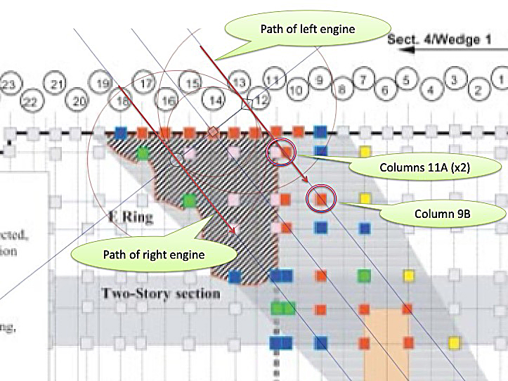
So, what about the E Ring wall to the north? No, it’s not a cloud without resistance. But in the face of hundreds of MJ of imagined impact energy, it’s clearly amenable to entry. After attenuation of overall energy by the fuselage breach and starboard collision, velocity is reduced to ~770 ft/s, and the left-wing root arrives incrementally. It’s useful to divide the wing into approximately 5-ft segments because of the tapering mass and tapered delivery, with the engine being its own unique segment. (A hypothetical 757’s left engine would’ve travelled directly into Columns 11A (x2) and Column 9B, but the curved damage to Column 9B must have been caused by another mechanism, since we’ve already ruled out impact by many other methods. See Fig. 16 to chart LPI’s proposed path.) The inner segments of wing, being more massive, deliver ~20 MJ, whereas the outer segments of wing, being less massive, deliver ~12 MJ. The left engine delivers ~100 MJ. That substantial energy delivered to the narrow surface area of the northern aspect of wall is enough to obliterate it. 12 MJ of impact energy is massive. XA1 was correct about the left wing.
The left side of the alleged aircraft would arrive with over 300 MJ of distributed energy. But it needs only ~50 MJ to eviscerate the first story of the E Ring façade, from the left-wing root at Column 13AA all the way to the left wingtip at Column 6AA. The “last but not least” part of the left wingtip still carries sufficient impact energy (~12 MJ) to slice through the cladding, brick, reinforced concrete, and Kevlar-backed wall. If the plotters had played their cards right, they would have successfully blasted their way down to the 6th column line. The E Ring wall between Columns 6AA and 8AA ought to have been obliterated, but, as shown in XA1 Fig. 2, it was not. XA1’s claim stands.
An illogical implication drawn by LPI authors is that the right wing impacted the building with more energy but delivered less damage (i.e., to Columns 15, 16, and 18, which remained standing), whereas on the northern side, where the left wing would have delivered less energy, it did more damage (i.e., Columns 10–13 were completely missing). Proponents of a large plane impact theory cannot have it both ways. And, as shown by the calculations above, their scenario is mathematically impossible. No large airliner impacted the Pentagon façade that morning. Math and material science will not allow that notion to persist.
So, how did the steel tubing near column 9AA get bent and twisted, while the adjacent column, though warped and weakened, was not obliterated by the ~60 MJ that an aircraft’s mid-wing might deliver?
The damage is best explained by explosives. LPI2 Fig. 14A demonstrated a possible debris dispersion pattern from E Ring placed charges. Fig. 17 below illustrates the same. LPI2 Fig. 14B illustrated a damage pattern extending toward the C Ring breaching hole. This observer is not dissuaded from discerning that multiple pieces of ordinance would have been required, including within the C Ring as well as within the Naval Command Center (which is not mentioned in LPI2’s graphic).
LPI2 Fig. 15 showed the uplifted floor slab discussed in XA1. Notice that the slab is pitched like a tent, with each half intact and raised as a unified body. That is the result of explosive overpressure acting upon the area in one sustained force. Kinetic impact from an engine’s gyroscopic procession would leave a shattered mark in the heavy slab—that is, if it could move the 45,000 lb slab at all. It would require more than 75,000 lbs of uplifting force, which would be readily achieved by the overpressure of an internal explosive. There’s a lot of energy in a rotating RB211-535E4 engine, but it would be ripped apart as it bounced off the slab and columns on its way to the D Ring. Transferring that energy into a vertical component with sufficient energy to uplift an intact span of slab would be exceedingly unlikely. The buckled slab is most consistent with explosive overpressure, perhaps from a 5–10 MJ explosion.
An explicit description of all the 5–10 MJ charges needed, a determination of which ones worked and which ones failed, and an explanation of the type of diesel-augmented fuel-air explosive (FAE) and/or other thermobaric weaponry then available are beyond the scope of this ongoing challenge to LPI’s assessment of the E Ring damage. Note that in XA1, I said, “We should not expect the fuel-air explosion of an exploding airliner to have the impulse to bend steel-reinforced concrete columns.” That does not rule out the use of other types of FAE ordinance, which could have bent the columns, such as then-novelly developed nanocomposites with fuel additives.
Fig. 18 below clarifies the alarming features of XA1 Fig. 5. This image is evidence of significant overpressure within the building. The deflections are not consistent with a 52-degree kinetic impact, and a deflagrating airliner could not bend those columns. XA1’s claims remain undefeated.
LPI2 mischaracterized the origin of my assertion that we were told the plane impacted the building at a left banking angle. This assertion had nothing to do with the Gannett Media witnesses who were strategically found on the bridge. Rather, the left bank interpretation comes from the ASCE report, which attempted to align the right engine with the generator and the left engine with a low retaining wall. That interpretation placed the plane at an angle, and when planes are at an angle, they are often banking.
However, if any witnesses did explicitly report a banking airplane that day, it was the collection of coherent witnesses who testified that they observed a white airplane bank to the right and pull up after flying north of the Citgo gas station. Citizen Investigation Team (CIT) diligently documented those witness testimonies. Enumerating them here would be beyond the scope of this E Ring response.
LPI2 brought up the security footage, which appears to show an object impacting the building. Due to space limitations and rules of engagement, I cannot complicate this response by reviewing the security gate cam footage that was released in 2002. An exhaustive deconstruction of the flawed footage from that camera can be found at PentagonTruth.org. A snapshot of the findings is shown here (see Fig. 19 below).
LPI2 Fig. 17 shows the bent fence post, bent cleanly at the ground and bent directly toward the building. I appreciate the additional image, which shores up my argument in XA1. Please see Fig. 7 earlier in this reply for a reminder of how vantage point can change perceived vector.
As for the notion that a large truck left a mark: Yes, that’s still the most viable interpretation. We have no images of the lawn that morning before explosions drew everyone’s attention in that direction. The fence post could have been toppled long before Arlington FD arrived. Maybe there was an accomplice in the vicinity with special equipment? Maybe he set the stage? We don’t know what we don’t yet know. We do know that an airliner impacting that fence post at the alleged velocity would have sheared the top of that post, and the fence post would not have the sustained radial bend at the base. The bend, therefore, is better explained by the force of a large truck with a low bumper.
I’ll mention that LPI2 ignored the point about the northern fence being swept into the building by the left wing had there been a plane impact. The important question was not “How was the fence blown outward?” but rather “Why wasn’t the fence pulled inward?” In other words, XA1 showed that the geometry of alleged impact aligned with a more northern wing sweep against the façade. This paper confirms the geometry and shows that the forces involved would have been immense. The northern fence should have been ripped toward and even into the building via conservation of momentum, just as a 757’s left wing would have ripped into the building, all the way to Column 6AA.
In the face of a flawed façade, we must retrace the purported flight path to find additional areas of subterfuge. I’ll mention a few such areas below.
The portable diesel generator trailer was heralded by the early mythmakers as “proof” that a large airliner hit the building. XA1 showed that it was likely pushed over by a truck, knocking it toward the building but also pivoting the assembly slightly toward the south.
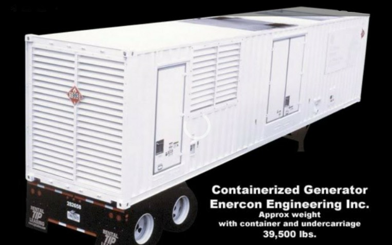
Those portable containerized diesel generator trailers often weigh as much as 40,000 lbs, though I made a mistake in the XA1 analysis by citing only 30,000 lbs. See the 39,500-lb example trailer provided in Fig. 20 below. The probability of eastward displacement of a ~40,000-lb generator due to airline engine impact with the upper aspect of its steel shell is only about 0.1%.
This is because at 777 ft/s the trailer would only endure 0.0165 s of contact time with the right engine. If the trailer weighed ~40,000 lbs and was displaced by 0.384 radians (22 degrees) over about 1 s of swing time, pivoting on its SW corner as shown in XA1 Fig. 21, its required angular acceleration is ~26 rad/s^2. Using a standard formula for a rectangle pivoting at its corner, the moment of inertia is ~2,800,000 kg x ft^2. The required torque is thus the moment of inertia times the angular acceleration, which yields a required torque of about 73 million ft x lbf.
The right engine would impact the trailer’s thin upper shell of 2 mm steel, sheering it easily with only about 10,000 lbf in resistance. Even brief resistance from the upper aspect of any impacted alternator frame within the trailer would only add up to 300,000 lbf based on resistance of heavier materials. It’s reasonable to approximate the total drag on the right engine at about 200,000 lbf over the 0.0165 s contact time. Applying that force by the effective lever arm of an impact at 52 degrees, about 15 ft from the pivot point, yields an actual torque of about 2.3 million ft x lbf. This far less than the 73 million ft x lbf required to rotate the trailer 22 degrees. Thus, the distributed odds of this occurring are less than 1%.
As shown in XA1 Fig. 21, a 757 at 530 mph would have hit that trailer top and moved it in a more northeasterly direction. The >20-degree clockwise displacement of the trailer is not feasible given the minimal resistance provided by the thin metal shell of the upper aspect of trailer. Considering collision with the steel struts, the 0.0165-sec contact time is still insufficient to move that trailer 20 degrees to the east. Since it could not be moved in that manner by an impacting aircraft and since no aircraft struck the 18th column line in any manner, we deduce that it was moved by some other mechanism. The bent fence post illustrated in XA1 Fig. 26 points toward force applied by a large truck. It’s conceivable that the generator was partially staged before any explosive events drew attention to the scene.
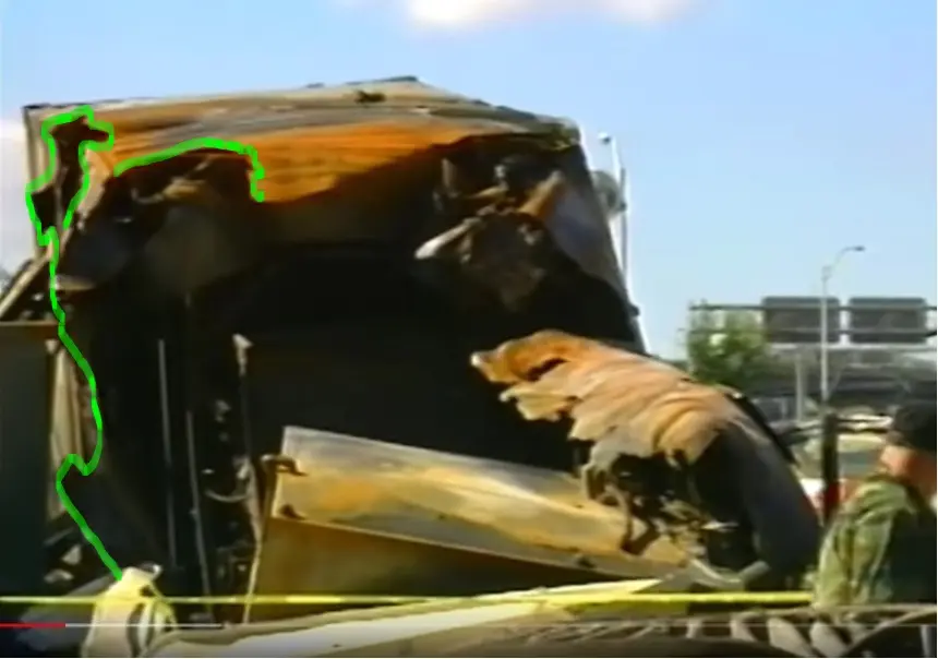
And, as the LPI authors seem prone to do, they have ignored the key finding of XA1 Fig. 25, redemonstrated here in Fig. 21 below. The southern aspect of the eastern wall of the trailer was decimated. The western wall of the trailer was likely curled inward from heat. The totality of the damage is best explained by an explosion, especially considering that we’ve already discerned manipulation of the movement of the generator itself. So, the generator could have been moved first and then been blown up, concurrent with the rest of the effects.
LPI authors and the ASCE propose that a 180,000-lb airliner rolled to the left from the impact with the generator’s lightweight trailer top. That alleged leftward roll leads them to surmise that the left engine might have impacted the low retaining wall. Could the airplane have rolled left to that extent? On page 29 of XA1, I implied that such a roll would not be possible in such short duration. The dilemma is that it would have had to occur within the travel time from right engine impact with the trailer to left engine impact with the wall. The force applied by the right engine collision is just not enough to cause many feet of left engine drop. An exhaustive analysis will likely reveal that the left engine can only be displaced by inches in that short travel time.
Hypothetically, if there were drag upon its right engine, an aircraft would indeed roll toward the left, around its center of gravity. But the retaining wall was .039 seconds (secs) away from the trailer. XA1 Fig. 21 shows that the trailer was moved about 22 degrees to the east. If an impacting airliner moved the trailer, then drag would be mitigated and any counterclockwise torque would have been reduced. We might anticipate up to 14 degrees of overall left roll (XA1 spoke of “left bank”) but a total vertical displacement of only inches in that .039 secs travel time. LPI1 argued that the aircraft’s inertia was overcome by ~0.02 secs of interaction with the trailer and that the left engine dropped 8-to-10 feet in 0.039 secs of flight. Such swift vertical displacement would require orders of magnitude more torque than could possibly be provided by the trailer impact. See Figures 22 and 23 below to note the disparity in impact heights.
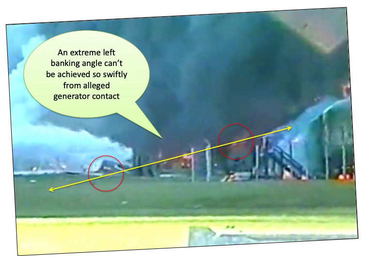
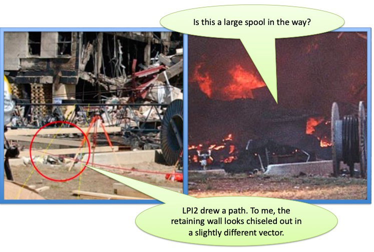
LPI2 ignored several of XA1’s crucial points regarding the retaining wall and the impossibility of the extreme leftward roll. The authors focused instead on the angle portrayed by the damage. For comparison, in Fig. 24 below, I’ve placed a portion of LPI2 Fig. 19 next to an image taken immediately after the event.
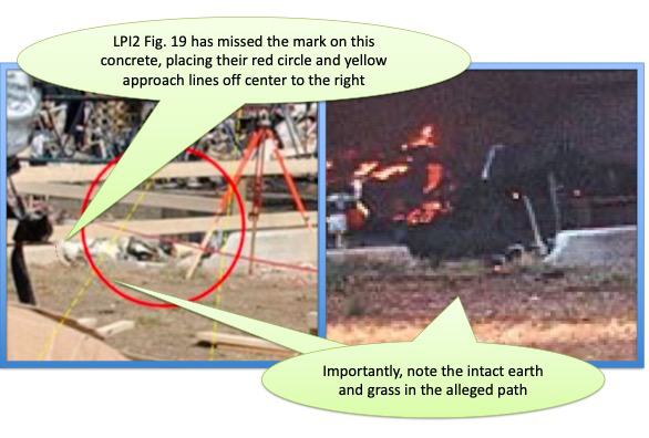
LPI2 did not respond to XA1’s observation about the lack of damage to the earth. Fig. 25 (above) illustrates the unadulterated earth.
Also, LPI2 neither attempted to reconcile the location of the left wing nor commented on the plausibility of such an extreme bank/roll given the prescribed approach. Though the LPI authors and I disagree with the angle of implied approach apparent from the damage as well as with how that damage happened (by an airplane or by sabotage), I submit that there are lots of ways to make something achieve a certain “look.”
But if the mechanism used to describe why something looks a certain way is not physically possible, then the theory about that mechanism is wrong. It doesn’t matter if the theory sounds nice or is unified or convenient. If the individual components that make up a narrative are demonstrably flawed by the reality of fundamental physics, that theory is wrong. According to physics, a large aircraft could not have dropped that many feet in .039 seconds of travel time. XA1’s analysis holds. The LPI theory is wrong.
LPI authors invoked Occam’s razor, as though violating a philosophical axiom is worse than defending theories that violate physical reality. If simple answers were truly sufficient, why did anybody ever question the 9/11 official narrative in the first place?
Rather than dismiss these incrementally derived pieces of evidence, which help us further develop what truly transpired, this author seeks to accurately provide as many piecemeal datapoints as possible. In that way, we all might have a truer constellation of understanding, and more will ultimately be illuminated. Seeing the curved shape of remnant rebar and insinuating it must be from an engine impact, as was done in LPI2 Fig. 20, is ludicrous in the face of the abundant energy abnormalities. A new collective conclusion must be made. That is the imperative.
Some unassailable E-Ring datapoints that the XA1 and XA2 arguments have brought forth thus far are:
- Total wall damage was not wide enough for a 757 to have flown through at that angle of approach.
- Existing wall damage was not severe enough, and damage was missing completely at the third story.
- Fencing would have moved toward the building if it had been swept by a wing.
- Columns were bent in the wrong direction for the prescribed kinetic approach.
- Airliner FAE cannot explain the bent columns, therefore other FAE ordinance types must.
- Critically, column 18 was fully intact after the alleged impact!
- Other important columns did not exhibit interaction with the energy of an inbound airliner.
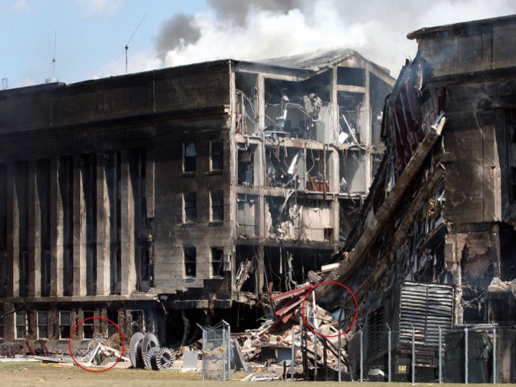
- Spools on the lawn were still in the way after the “event.”
- There was irreconcilable generator displacement to the east.
- The LPI/ASCE retaining wall explanation and physics do not agree.
- Energy disparities abound in the LPI/ASCE version of events.
- RADES data placed the target north of the bridge, in alignment with the north-of-Citgo witnesses.
I don’t envy those who argue that a large plane impact occurred. They face an impossible challenge. While some of their defenses are correct conceptually, they are wrong computationally. Yes, there is yaw, but not enough. Yes, there would be roll, but not that fast. Yes, an impactor would lose energy, but not meaningfully. And yes, poisoned breadcrumbs have been dropped to keep the fairy tale alive. But in the face of physics, the ASCE and LPI version of events at the Pentagon is refuted. “Large Plane Impact” has been falsified.
References
Indiana Limestone Handbook, 22nd ed., Indiana Limestone Institute of America.
Mlakar, Paul E., et al. “The Pentagon building performance report.” American Society of Civil Engineers, 2003.
https://www.facebook.com/watch/?v=543861495999454
https://archive.org/details/FAA_RADES_NORAD_FOIA_Data
https://archive.org/details/FBI_FOIPA_1141552_PENTAGON_WRECKAGE
https://archive.org/download/NTSB_AAL-77_UAL-93
https://www.citizeninvestigationteam.com/official-interviews
https://www.history.navy.mil/research/archives/Collections/operational-records/ops-p/pentagon-attack-narrative-accounts.html