The “Analysis of Structural Response of WTC 7 to Fire and Sequential Failures Leading to Collapse” (McAllister et al. 2012) published by the American Society of Civil Engineers (ASCE) presents a complex procedure used to analyze the structural behavior of Seven World Trade Center (WTC 7) on September 11, 2001. The authors concluded that the catastrophic global collapse followed local connection and framing failures induced by office fires on several floors. Although the authors included a brief discussion of the relationship between simulation results and observed events, the paper lacks any objective discussion of the practical application or significance of the computational modeling described.
The technical paper published in the Journal of Structural Engineering summarizes, but necessarily condenses, many details found in the National Construction Safety Team Act Reports NCSTAR 1A (Sunder et al. 2008), NCSTAR 1-9 (McAllister et al. 2008) and NCSTAR 1-9A (MacNeill et al. 2008) published by the National Institute of Standards and Technology (NIST). However, the paper lacks references to public sources of information sufficient to verify the authors’ assumptions and conclusions. For example, structural calculations demonstrating the “walk-off” failure mechanism that hypothetically triggered the progressive collapse are unavailable. This information was placed off limits in 2009 when the NIST Director determined that release of calculations “might jeopardize public safety” (Gallagher 2009). If released, according to NIST, the calculations “would provide instruction to individuals wanting to learn how to simulate building collapses and how to most effectively destroy large buildings” (Kollar-Kotelly 2011). But the Ethical Standards for ASCE Journals are clear; technical papers are required to include “detail and reference to public sources of information sufficient to permit the author’s peers to repeat the work or otherwise verify its accuracy.” This standard aligns with the engineer’s responsibility for ensuring public safety and has nothing to do with devising ways to destroy buildings.
Although structural calculations demonstrating the “walk-off” failure mechanism are unavailable, many structural design, fabrication and erection drawings of WTC 7 were released by the NIST Freedom of Information Act (FOIA) office and are available for those interested in studying the building’s structural system. A comparison of original construction documents with details of the NIST study raises numerous questions germane to the collapse initiation. This discussion summarizes several of these questions.
Shear Studs and Composite Floor Construction
The discussion of lateral-torsional buckling of beams and girders implies that all interior girders in the building lacked shear studs providing composite action with the concrete floor slab, and the lack of shear studs contributed to collapse initiation and extensive floor-framing failures throughout the structure. McAllister et al. 2008 shows the girder spanning between columns 44 and 79 at floor 13 lacked shear studs, and this agrees with Cantor (1985) structural drawing S-8 revision H. But a previous publication describing the fabrication and construction aspects of the
steel structure clearly shows 30 shear studs equally spaced along this girder at typical office floors including floor 13 (Salvarinas 1986). The author, John J. Salvarinas, was the project manager for Frankel Steel Limited (one of the two steel fabricators) during the construction of WTC 7.
In addition to Salvarinas 1986, the steel erection drawings for typical office floors (drawings E8/9 through E20 and E24 through E44/45, Frankel Steel 1985a) note: “FOR ADDITIONAL STUDS SEE CUST. DWG. S8 REV. I“. Cantor (1985) sheet S-8 released by the NIST FOIA office includes revision H but not revision I. Sheet S-8-10 revision I clearly shows 30 shear studs on the corresponding girder at floor 10. Sheet S-8-19 revision I shows an additional bottom flange plate on this girder and no shear studs on the secondary beams east of the girder at floor
19. Sheet S-8-20 revision I clearly shows 30 shear studs on this girder and an unidentified number of studs on the secondary beams at floor 20. The “as-built” conditions of typical office floors are unclear considering these variations and incomplete notations on the structural drawings.
These variations and contradictions were not addressed by McAllister et al. 2012 or the NCSTAR reports. Was sheet S-8 revision I included in the construction documents for typical office floors? Did the authors consult the design/construction team to clarify these discrepancies? How did the authors confirm that shear studs were in fact omitted from the girder(s) at floor 13 and at typical office floors? The ANSYS collapse-initiation model and its conclusions would be invalid if there were shear studs on these interior girders.
Girder Restraint Versus “Walk-off” Failure
McAllister et al. (2012 and 2008) made numerous references to “walk-off” failures due to thermal expansion. The technical paper states:
Under elevated temperatures, a beam could lose vertical support at its ends through connection failure, including walk-off of a beam support seat. Walk-off failure is attributed to either (1) movement along the axis of the beam resulting from sagging of beams or girders, or (2) lateral displacement of a girder resulting from thermal expansion of beams framing into the girder. Gravity loads in a beam are transferred to the bearing seat from the bottom flange of the beam near the web. Therefore, when the web was no longer supported by the bearing seat, the beam was assumed to have lost support, as the flexural stiffness of the bottom flange was assumed to be insufficient to transfer the gravity loads. Under such a condition, the beam was removed. Although axial walk-off was possible, the computed connection failure was in all instances by lateral walk-off.
Axial walk-off was not possible. The maximum vertical deflection (sagging) of the W33x130 girder was less than two inches (51 mm) due to service loads including dead load plus 25 percent of the office-floor live load, so the resulting axial movement due to sagging was practically zero. This deflection calculation includes a stiffness reduction for elevated temperature up to 1,200 degrees F. (650 degrees C.) The critical girder was also restrained from excessive axial movement between the web of column 44 (drawing 9102, Frankel Steel 1985b) and the flange of column 79 (drawing 9114, Frankel Steel 1985b). An axial displacement of 6.25 inches (159 mm, McAllister et al. 2008) leading to “walk-off” was simply not possible.
The technical paper lacks any discussion of the LS DYNA partial-floor model that was used to develop possible failure modes of floor framing and connections. McAllister et al. 2008
describes how thermal expansion caused high-strength bolts to shear off at each end of the critical floor 13 girder and how the girder elongated enough to bear against the north face of column 79. This girder was restrained from excessive lateral displacement at column 44 by the column flanges as shown in fabrication drawing 9102 (Frankel Steel 1985b). Was the girder also restrained from excessive lateral displacement at column 79 by the side plates projecting past the column flange as shown in fabrication drawings 1091 and 9114 (Frankel Steel 1985b)?
McAllister et al. 2008 lists observed failures in the partial-floor model, but lateral “walk-off” of the girder from its seat is not listed. The authors need to clarify how lateral “walk-off” occurred considering these physical restraints at both ends of the girder and how “walk-off” was verified as a possible failure mode.
The Column 79 Bearing Plate
The 16-story ANSYS model included detailed framing connections for floors eight through 14 on the east side of the building. The analytical model for the seated-beam connection at column 79 (McAllister et al. 2008) was compared to fabrication drawing 1091 (Frankel Steel 1985b).
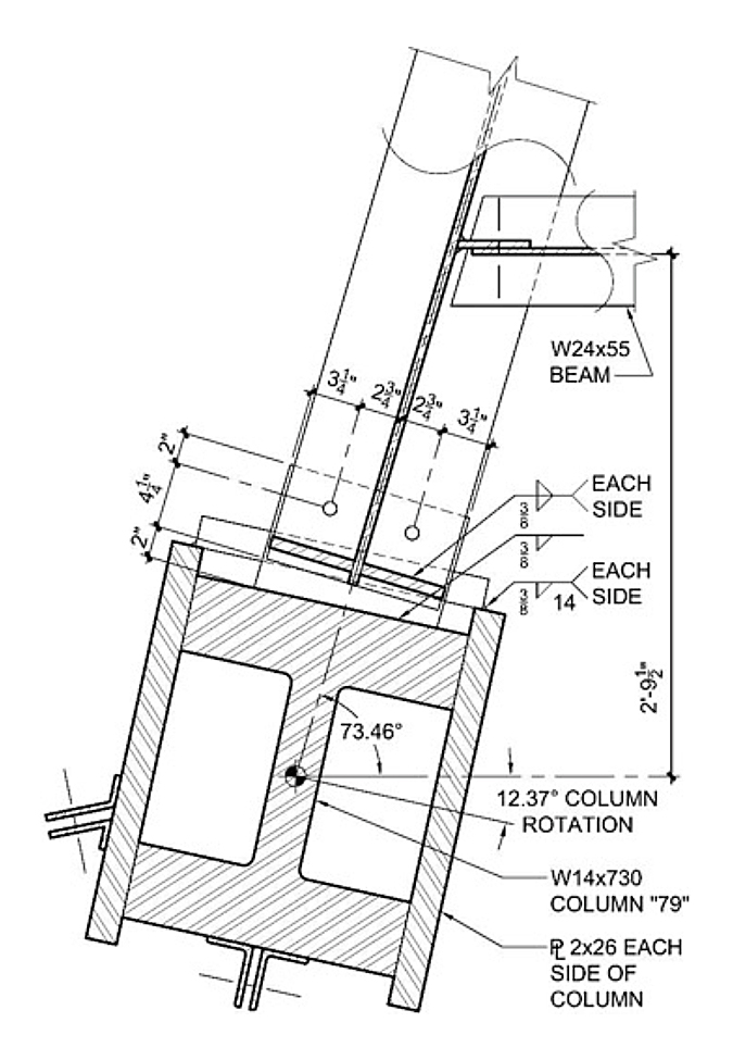
This drawing illustrates the column 79 assembly at floor 13. The one-inch (25 mm) thick bearing plate supporting the girder was 12 inches (305 mm) long providing full support for the girder’s bottom flange. But the ANSYS model only accounted for an 11-inch (279 mm) long bearing plate—shorter than the flange width. According to the ANSYS analysis, a lateral displacement of
5.5 inches (140 mm) was reported to cause a loss of vertical support leading to removal of the girder from the model (McAllister et al. 2008). The girder web, however, was still supported by the bearing plate after a 5.5-inch (140 mm) lateral displacement—or less than half the bearing plate length. Why did the ANSYS model incorporate a length reduction for the bearing plate?
The NIST WTC Investigation Team addressed this question in an addendum to its errata file (McAllister 2009) dated June 27, 2012:
The 16-story model of WTC 7 used a 12 in. bearing plate on the north side of Column 79, consistent with Frankel drawing 1091. The 5.5 in. dimension was incorrectly cited, as the
6.25 in. dimension accounted for the lateral walk-off distance. These changes correct typographical errors. The dimensions and lateral displacements used in the analyses were correct.
The 5.5-inch (140 mm) and 6.25-inch (159 mm) dimensions were transposed in NCSTAR 1-9 (McAllister et al. 2008) according to McAllister 2009.
The 5.5 in. dimension was the length of the girder bearing on the seat connection that had to slide off the seat axially to the girder. The 6.25 in. dimension accounted for the length from the flange tip to the far side of the web, so that the web was no longer supported on the bearing plate.
How did the NIST WTC Investigation Team arrive at a 5.5-inch (140 mm) threshold for axial “walk-off” of the girder at column 79? The bearing length at column 79 was 6.25 inches (159 mm) along the girder’s axis as shown on fabrication drawings 1091 and 9114 (Frankel Steel 1985b), and the girder was restrained between columns 44 and 79.
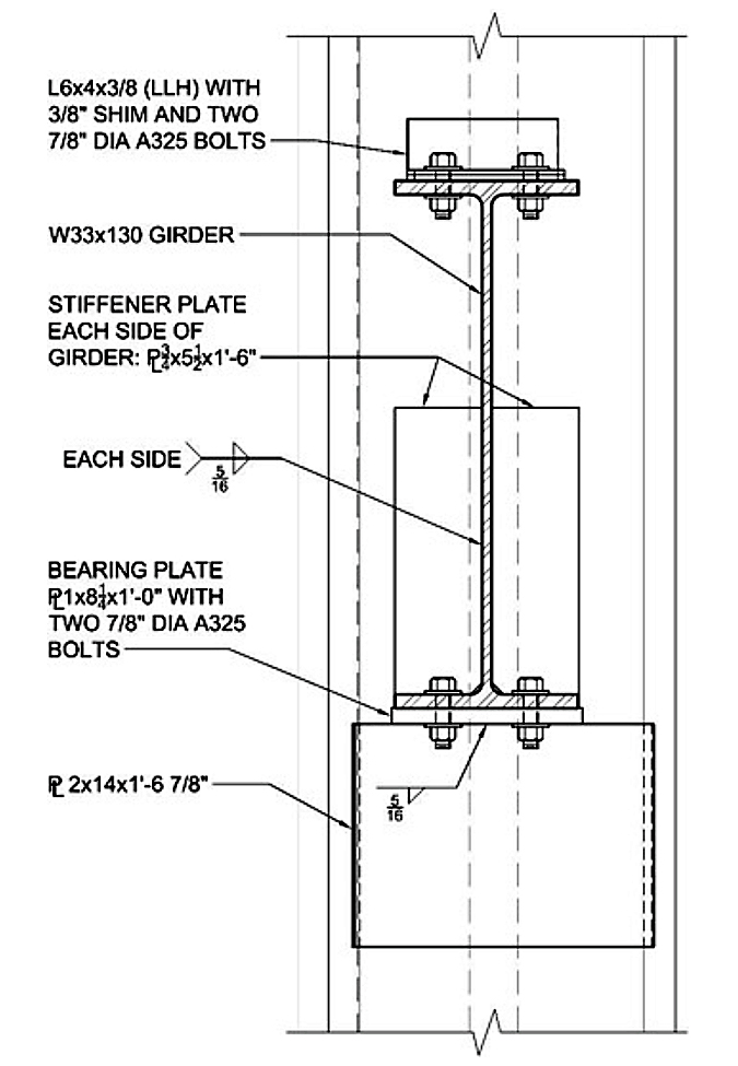
Could “walk-off” occur with a 6.25-inch (159 mm) lateral displacement? Figure 1 illustrates a plan view of the seated-beam connection with dimensions and geometry shown to scale. Figure 2 shows the same connection in a section view through the girder. The one-inch (25 mm) thick bearing plate was 12 inches (305 mm) long and 8.25 inches (210 mm) wide at its widest point.
Stiffener plates were welded on each side of the girder web.

Web-Flange Stiffeners
The analytical model for the seated-beam connection at column 79 (McAllister et al. 2008) does not account for the presence of stiffener plates as shown in fabrication drawing 9114 (Frankel Steel 1985b). This drawing illustrates ¾-inch (19 mm) thick partial-height web stiffeners welded to the girder web and bottom flange directly over the bearing surface. Fillet welds connecting the
stiffeners were adequate to transfer the vertical shear from the girder web to the stiffeners, and a lateral displacement of 6.25 inches (159 mm) would not necessarily cause a loss of vertical support. The authors’ assumption that the flexural stiffness of the girder bottom flange was “insufficient to transfer the gravity loads” is untenable. Why were these stiffeners omitted from the ANSYS connection model when they obviously affect the bending characteristics of the girder bottom flange?

These are a few of the questions raised by examining the construction drawings and comparing them with details of the authors’ collapse-initiation hypothesis. Initialization of the 47-story global model with the ANSYS results led to instantaneous floor failures, and Table 1 (McAllister et al. 2012) implies these cascading floor failures were observed before column 79 buckled and the east penthouse began falling. This is speculation, and detecting an east-west vibration by video analysis does not demonstrate girder “walk-off” failures or cascading floors.
NFPA 921 Guidelines
Clear guidelines for structural fire investigations were established by the Technical Committee on Fire Investigations (TCFI) for the National Fire Protection Association (NFPA). The scientific method of NFPA 921 (TCFI 2001) requires an objective analysis of the facts and careful attention to all relevant details. TCFI 2001 states: “Subjective or speculative information cannot be included in the analysis, only facts that can be proven clearly by observation or experiment.” The NIST investigation of WTC 7 did not follow the basic methodology outlined in NFPA 921—the national standard for fire investigations. Furthermore, an objective analysis of the facts and careful attention to relevant details are not exclusive to NFPA 921; these should be the cornerstones of any comprehensive investigation.
The destruction of WTC 7 on September 11, 2001 and the final NCSTAR reports issued in 2008 raise many questions in addition to those outlined here, but one thing is certain: Thousands of hours of computer simulation are no substitute for a forensic investigation based on published national standards and well-established principles of scientific inquiry.
References
- Cantor, Irwin G., P.C. Structural Engineers (1985), Structural Drawings, 7 World Trade Center.
- Frankel Steel Limited (1985a), Erection Drawings, 7 World Trade Center.
- Frankel Steel Limited (1985b), Fabrication Shop Drawings, 7 World Trade Center.
- Gallagher, Patrick (2009), “Findings Regarding Public Safety Information”, NIST, July 9.
- Kollar-Kotelly, Colleen (2011), “Memorandum Opinion, Michael Quick v. U.S. Dept. of Commerce, NIST”, Civil Action 09-02064 (CKK), U.S. District Court for the District of Columbia, April 7.
- MacNeill, Robert et al. (2008), NIST NCSTAR 1-9A, “Global Structural Analysis of the Response of World Trade Center Building 7 to Fires and Debris Impact Damage”, Washington: U.S. Government Printing Office, November.
- McAllister, Therese P. et al. (2008), NIST NCSTAR 1-9, “Structural Fire Response and Probable Collapse Sequence of World Trade Center Building 7”, Washington: U.S. Government Printing Office, November, pp. 342-343, pp. 349-354, pp. 482-483, p. 527.
- McAllister, Therese P. (2009) Errata for NIST NCSTAR 1A, NIST NCSTAR 1-9, and NIST NCSTAR 1-9A, Federal Building and Fire Safety Investigation of the World Trade Center Disaster: Structural Fire Response and Probable Collapse Sequence of World Trade Center Building 7, January 30. Updated June 27, 2012.
- McAllister, Therese P. et al. (2012), “Analysis of Structural Response of WTC 7 to Fire and Sequential Failures Leading to Collapse”, Journal of Structural Engineering, Vol. 138, No. 1, pp. 109-117.
- Salvarinas, John J. (1986), ”Seven World Trade Center, New York, Fabrication and Construction Aspects”, Canadian Structural Engineering Conference Proceedings—1986, Canadian Steel Construction Council, Willowdale, Ontario, pp. 11-1 to 11-44.
- Sunder, S. Shyam et al. (2008), NIST NCSTAR 1A, “Final Report on the Collapse of World Trade Center Building 7”, Washington: U.S. Government Printing Office, November.
- Technical Committee on Fire Investigations (2001), “NFPA 921 Guide for Fire and Explosion Investigations, 2001 Edition”, National Fire Protection Association, Inc., Quincy, MA.


